


3
Table Of Contents
Important Notice
4
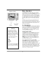
Principle of Operation
5
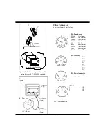
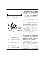
Display Unit Installation
6
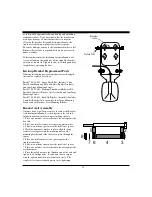
Selecting the transducer Configuration for Your Boat______________________________________ 8
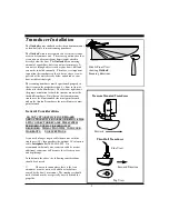
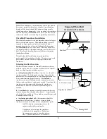
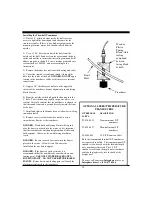
Transducer Installation
9
Basic Operation
16
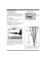
Getting Started
17
Set-Up View
18
Demo Program
18
Units of Measure
19
Language Selection
19
Level Adjustment
19
FWD View (Full Screen Forward Scan)
20
Range Adjustment
20
Sensitivity Adjustment
20
Alarm Adjustment
20
Scanning Speed (Resolution) Adjustment
21
Down View
22
Range Adjustment
22
Sensitivity Adjustment
22
Bottom Hardness
23
Alarm Adjustment
23
Zoom & Bottom Track
23
Data View
25
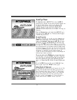
Interpreting Your Outlook Display
26
Distance Forward
27
Noise and Sensitivity Adjustments
27
Transducer Sidelobe Effect
27
Frequently Asked Questions (FAQ’s)
29
Maintenance
30
Troubleshooting Guide
31
Interference Problems
32
Specifications
33
How To Obtain Service
34
Warranty
35
Summary of Contents for Outlook
Page 1: ...1 OPERATION MANUAL...
Page 36: ...36...


