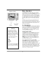
background image

General Information 


T

hank you for your selection of the 

Interphase Outlook 

Forward Scanning Sonar.  The 

Outlook’s ruggedly built, 

compact design makes it ideal for installation on nearly any 

boat.  It will display water depth, bottom conditions and 

submerged objects such as fish, or objects in your path, on its 

high resolution display.  The 

Outlook is available with either a 

transom or thru-hull scanning sonar depth transducer.  


The 

Outlook allows operation in your choice of nine 

languages: English, French, Italian, Spanish, German, Danish, 

Finnish, Swedish, or Greek.  Power-off memory saves 

language, depth range, gain and contrast settings, screen 

advance speed and location in screen menu.   


To ensure that you receive the maximum benefits available 

from the outstanding features of the 

Interphase Outlook

please carefully follow the steps outlined in this manual.  An 

instructive demonstration simulator has been designed into the 

Outlook and we highly recommend that you spend some time 

using the demo mode prior to actual use of the unit.  We also 

recommend that you read this entire manual before attempting 

to either install or operate your 

Outlook. 


Warranty Information


Interphase provides a limited warranty on the Outlook 

Forward Scanning Sonar which is printed on the inside rear 

cover of this manual.  We recommended that you save all 

packing materials so that if you should need to send in the unit 

for repair, it can be fully protected.  Should you experience a 

problem with your 

Outlook, first refer to the Troubleshooting 

section (Page 31) of this manual.  Most common problems and 

their solutions are described here.  If problems persist, call 

Interphase Product Support at (831) 477-4944.  We will be 

happy to try to assist you, and if required, we will give you 

instructions on how to quickly get your set repaired. 


The enclosed warranty registration card must be completed 

and returned to 

Interphase within 15 days of purchase so that 

your unit may be protected under the warranty.  Failure to 

return the warranty card may cause unnecessary delays in 

processing your unit for warranty repair. 


WARNING 

Navigation based solely on one method or 

one instrument should never be practiced.  

While the 

Outlook can be quite useful in 

showing underwater structure and changing 

bottom conditions both below and in front 

of your vessel, there are many situations 

and conditions which can cause erroneous 

or distorted readings. 


In addition, there are many situations that 

can cause “blind spots” in the 

Outlook’s 

field of view including the presence of 

temperature inversion layers (thermoclines), 

water turbulence, and high concentrations 

of suspended particles in the water. 


While the 

Outlook can be considered as a 

useful aid to navigation, it should never be 

the 

only means of navigation. 

IMPORTANT NOTICE 


Since the 

Outlook’s Forward Looking 

technology is revolutionary, there is a 

strong possibility that we will develop 

many new and exciting features in the 

future.  We would like to make sure we can 

send you information about these new 

features and enhancements. 


Please fill out and return the Warranty 

Registration Card immediately.  This is our 

only method to keep in contact with you 

and we may want to advise you of future 

enhancements to your 

Outlook


If future changes or improvements are 

made, software upgrades will be available 

for a nominal charge. 

Summary of Contents for Outlook

Page 1: ...1 OPERATION MANUAL...

Page 2: ...n decisions were made We feel proud of the Outlook Forward Scanning Sonar and your satisfaction is very important to us To this end we welcome any comments or suggestions that you might have in regard...

Page 3: ...ew Full Screen Forward Scan 20 Range Adjustment 20 Sensitivity Adjustment 20 Alarm Adjustment 20 Scanning Speed Resolution Adjustment 21 Down View 22 Range Adjustment 22 Sensitivity Adjustment 22 Bott...

Page 4: ...roblems and their solutions are described here If problems persist call Interphase Product Support at 831 477 4944 We will be happy to try to assist you and if required we will give you instructions o...

Page 5: ...l single element depth sounders However when all elements in the array are sending or receiving acoustic energy at the same time the entire array behaves like a single larger element with one importan...

Page 6: ...aximum performance and life from your unit the following guidelines should be considered when selecting a mounting location 1 Select a location where the unit is protected from excessive temperatures...

Page 7: ...In Dash Bracket Installation Cable Connectors view from front of female plug 9 Pin Transducer 1 White 1st element 2 Brown 2nd element 3 Orange 3rd element 4 Yellow 4th element 5 Green 5th element 6 Bl...

Page 8: ...ide of the hull with the foremost face of the transducer even with the leading edge of the keel Alternatley the transducer may be placed forward of the keel ahead of the lifting strap location This sh...

Page 9: ...hull transducer Note that on the transom mount transducer the blunt rounded side must point forward and on the thru hull transducer the more blunt area must point forward General Considerations DO NO...

Page 10: ...is attached to the boat with a heavy duty stainless steel kick up bracket to provide protection against impact When the transducer strikes an object or the water force exceeds the resistance of the br...

Page 11: ...Mounting Screws Part 17 0056 008 Kick Up Bracket Assembly Includes Complete Bracket Axle Assembly four Large Mounting Screws and the Stainless Steel Mounting Bracket Bracket Axle Assembly On some boat...

Page 12: ...ucer and Spray Shield to the Bracket Locate the Stainless Spray Shield inside the transducer s stainless mounting ears Make sure spray shield is orientated as shown in sketch on the left Then assemble...

Page 13: ...ary with the type of boat Try to find a location with the smallest dead rise angle to make installation easiest a On displacement hulls sailboats trawlers etc locate the transducer about 1 3 aft along...

Page 14: ...ecessary use a fairing block to properly position the transducer Use of a Thru hull Fairing Block Nearly all vessels have some dead rise angle at the transducer mounting location If the thru hull tran...

Page 15: ...ut allow for swelling in wooden hulls 8 Remove excess sealant from the outside to assure smooth water flow over the transducer DANGER Wood hulls and fairing blocks will expand after the boat is put ba...

Page 16: ...which makes it easy to practice with the unit and to get a feeling for its many features before actually using it in real situations on the water We highly recommend you run through this section on op...

Page 17: ...View with Large Digit Detph on left and Forward scanning display on right SETUP Full Screen Set Up View Each of these views along with a sub menu which will allow you to change the range sensitivity...

Page 18: ...emonstration of its many features At any time you can press any key to gain control of the DEMO program to make your own selections and adjustments If you do not press any button for about 45 seconds...

Page 19: ...vertical to the water s surface This problem can be caused by improper installation or by changes in the boats fore aft weight When the boat is over a known level bottom the forward display should sh...

Page 20: ...erse video white on black To return to the main forward looking menu press the left soft key labeled LAST Note The Auto Mode will only work if the Outlook can find the bottom If the depth is greater t...

Page 21: ...ances beyond 100 feet Note the horizontal line will disappear a few seconds after the alarm is adjusted The Shallow Alarm is often used to alert the user to shallowing bottom conditions and the presen...

Page 22: ...il the button labeled AUTO is again selected Note when in the AUTO mode the soft key labeled AUTO will be shown in reverse video white on black To return to the main forward looking menu press the sof...

Page 23: ...en using the Down display conventional down looking view the Outlook can also display a split screen high resolution zoom of any 25 of the depth range or can show a split screen Bottom Track or Bottom...

Page 24: ...ack and the Bottom Lock features can be activated When the Bottom Track feature is activated the Zoom Bar changes to a thin bar extending from the top to the bottom of the display Pressing the ZOOM bu...

Page 25: ...al digits show the digital depth directly beneath the boat Notice that the menu in the DATA view is exactly the same as in the FWD view You can adjust the RANGE SENSITIVITY set an ALARM or select the...

Page 26: ...ustic beam from the bottom to the area ahead of the vessel the LCD display shows a continuously updated display of the return echoes in their approximate position in relation to the vessel Because the...

Page 27: ...tlook s transducer like all acoustic transducers does not form a perfect beam of acoustic energy Some of the acoustic energy is contained in an area called the sidelobes In conventional downlooking de...

Page 28: ...o helpful in minimizing sidelobe problems as shown in the diagram at right In the sketch a boat is shown with the main transducer beam aimed far forward However the sidelobe beam is also striking the...

Page 29: ...n shallow environments What type of transducer is needed and what does it look like The transducers for both Outlook are available in transom or thru hull configurations If you are operating an inboar...

Page 30: ...carefully remove any marine growth Use a mild detergent or 220 grit sandpaper or crocus cloth to remove stubborn growth 3 If the in line fuse is blown replace it with a 2 amp fuse NEVER REPLACE WITH...

Page 31: ...or there is excessive current from the battery The red wire should be positive and have continuity with pin 1 on the female side of the power supply lead Loses picture at speed Adjust the transducer a...

Page 32: ...tall an alternator filter to smooth the alternator s output signal Interference may also be caused by radiation from other nearby equipment and can be detected by turning off all other equipment and o...

Page 33: ...gth and Sounding Rates Automatically optimized for selected range Transmitter Power Over 400 watts RMS 3 200 watts peak to peak Power Requirements 10 5 to 16 VDC less than 0 5 Amp Dimensions 7 5 W x 5...

Page 34: ...2880 Research Park Drive Suite 140 Soquel CA 95073 In addition to speed your repair please fill out the following tear this page out of the manual or photocopy it and tape it to your unit for our tech...

Page 35: ...t to extreme conditions beyond control of the manufacturer and Interphase Due to these conditions the warranty on these components is limited to one year against defects in workmanship or materials Th...

Page 36: ...36...

Reviews: