


13
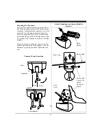
Thru-Hull Transducer Installation
The thru-hull transducer is the recommended choice
for larger boats with in-board engines. Thru-hull
mounting is usually required on larger power and
sail craft in order to find a mounting location free of
forward-looking hull obstructions. The PC/View
must have a clear view of the water ahead as it can
not see through obstructions such as the vessel’s
hull. Please read the following carefully before
starting the thru-hull installation.
Normally, thru-hull installations are performed by a
professional in a boat haul-out facility and we rec-
ommend that you seek professional assistance before
attempting to mount this transducer.
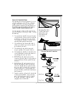
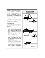
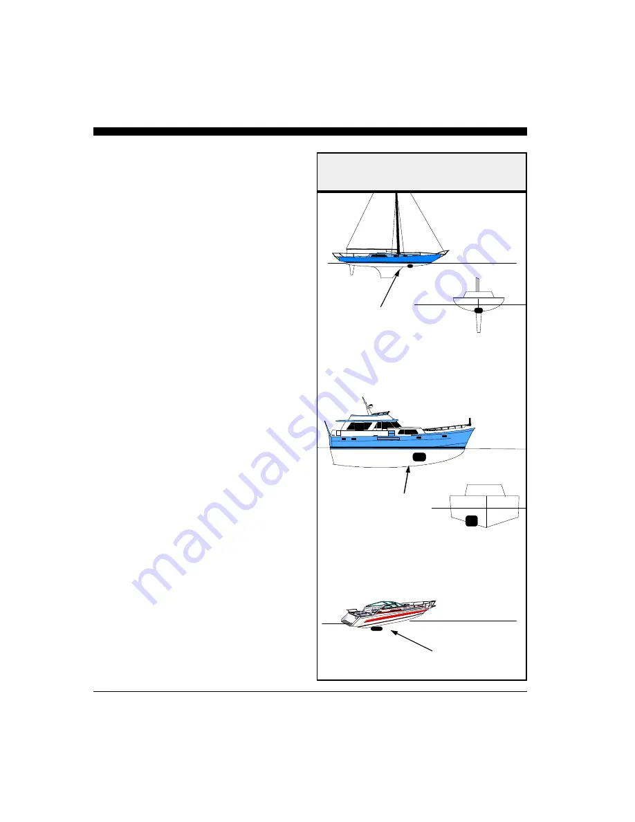
Selecting a Location
The best location to mount the thru-hull transducer
will vary with the type of boat. Try to find a loca-
tion with the smallest dead rise angle to make instal-
lation easiest.
a. On
displacement hulls
(sailboats, trawlers, etc.)
locate the transducer about 1/3 aft along the wa-
terline. Generally this provides the best compro-
mise between obtaining aeration-free water and
minimizing propeller noise. Water near the bow
and near the keel can be quite aerated. Since the
PC/View’s transducer can not see through aer-
ated water, it is best to mount the transducer
midway between these two areas.
b. On
sailboats
, the transducer should be mounted
where the acoustic beam will not be shaded by
the keel. A spot forward of a fin keel is usually
best. Try to find an accessible spot with a mini-
mum dead rise angle.
c. On
planing powerboat
hulls, the transducer
should be mounted well aft and close to the keel
to insure that the transducer is in contact with
the water at higher boat speeds.
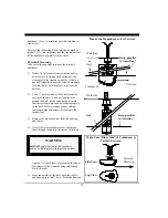
On inboard/outboard boats, transducer mounting
close to the engine usually yields good results.
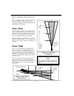
Suggested Thru-Hull
Transducer Locations
Fin Keel
Planing Hull
Displacement Hull
Summary of Contents for PC/View
Page 1: ...INTERPHASE INTERPHASE PC VIEW for Windows OPERATION MANUAL...
Page 54: ...54 W Warranty 6 7 55 Z Zoom 33...
Page 56: ...56...


