background image


15


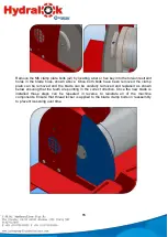
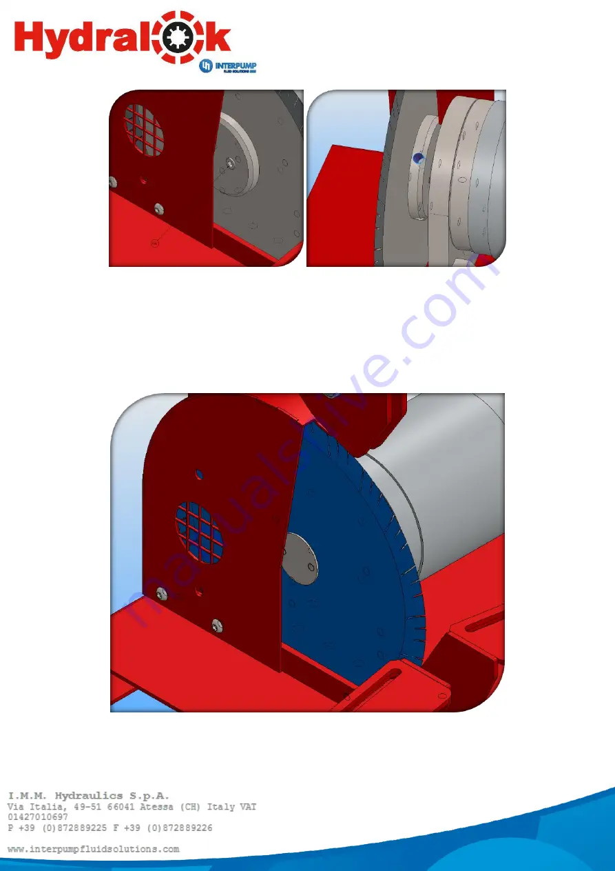
Remove the M6 clamp plate bolts (x2) by locating a bar or hex key into the torsion restraint 
holes  in  the  blade  boss,  shown  above.  Once  both  bolts  have  been  removed  the  clamp 
plate  can  be  removed  and  the  blade  can  be  carefully  removed  and  replaced  as  shown 
below ensuring that the teeth are pointing in the correct direction. Once the new blade is 
installed  these  steps  can  be  repeated  in  reverse  to  reinstate  all  of  the  machine 
components. Ensure that thread locker is applied to the blade clamp bolts on reassembly 
to prevent loosening over time. 


Summary of Contents for Hydralok HCLMOBILE

Page 1: ...USER MANUAL Electric hose cutting machine HCLMOBILE...

Page 2: ...PRELIMINARY CHECKS 7 LIGHTING 7 ROUTINE MAINTENANCE 7 MACHINE DESCRIPTION 7 OPERATING INSTRUCTIONS 7 MAINTENANCE AND SERVICE 8 GUIDELINES FOR CORRECTING CUT 8 BLADE WEAR 8 REPLACEMENT BLADES 8 Appendi...

Page 3: ...ers replacement and repair of any component found to be defective 5 Replacements and repairs completed under this warranty cannot extend its 12 months validity 6 This warranty does not cover any damag...

Page 4: ...Serial Number Description Electric hose cutting machine The machine is not included in the list of the Annex IV of Machinery Directive 2006 42 CE The machine complies with the requirements of Machine...

Page 5: ...perations are carried out by one operator only 4 This manual must be provided for the machine operator Ensure that the operator is aware of his her responsibilities 5 Guards must never be removed or t...

Page 6: ...12v 24v DC electrical supply by a qualified electrician Standard wire colour coding is applied where the RED wire terminal must be connected to the positive live supply terminal and the BLACK wire mus...

Page 7: ...be used for cutting steel wire reinforced rubber hydraulic hose or similar OPERATING INSTRUCTIONS To move the hose support pillars object 4 of Appendix 3 Machine Diagram unscrew the clamping handle 1...

Page 8: ...from the blade using the provided hose support pillars It is also essential that the bend is symmetrical about the cutting edge When cutting a hose the hose must not be slammed or forced unnecessarily...

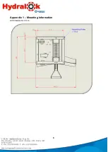
Page 9: ...9 Appendix 1 Mounting Information All dimensions in mm...

Page 10: ...10 Appendix 2 Wiring Schematic...

Page 11: ...11 Appendix 3 Machine Diagram...

Page 12: ...12...

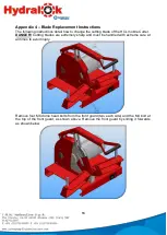
Page 13: ...e HCL mobile Cutter DANGER Cutting blades are extremely sharp and must be handled with extreme care at all times to avoid injury Remove four M6 dome head bolts from the front guard two each side and t...

Page 14: ...pivot block as shown above Note that the tension within the handle spring will attempt to work against this operation during undoing Pivot the handle and pivot linkages the cutting jaws and the pivot...

Page 15: ...p plate can be removed and the blade can be carefully removed and replaced as shown below ensuring that the teeth are pointing in the correct direction Once the new blade is installed these steps can...

Page 16: ...16 SPARE PARTS Part No Description CHBL250325D Toothed blade 250x3x25mm incl adapter 40 25mm CHBL250325 Smooth blade 250x3x25mm incl adapter 40 25mm...

Reviews: