Interroll Module belt conveyor SH 1100
Maintenance and repair
Version 1.0 (06/2022) en
Translation of original operating instructions
71
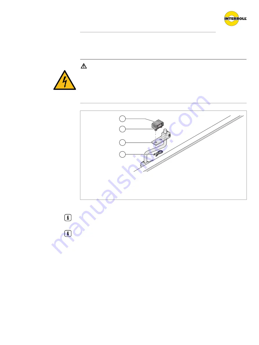
Replacing the photo cell and reflector
DANGER
Danger to life from electrocution and crushing
Installation and maintenance tasks on 400-V conveyor systems while they are in operation can
cause life-threatening electrocution and serious crushing.
4
Power down the entire conveyor module and ensure that it cannot be started accidentally.
Replacing the photo cell
4
3
1
2
Photo cell
1
Photo cell
3
Sensor holder
2
Photo cell housing
4
Fastening clip
The photo cell is replaced together with the photo cell housing and the fastening clip.
The fine adjustment of the photo cell is done with the vertical adjustment of the sensor holder on
the mounting bracket until it “sees” the reflector.
The electrical installation of the photo cell takes place after installing the reflector.
4
Loosen the fastening clip (4) under the sensor holder (3).
4
Remove old photo cell (1) and housing (2) from the sensor holder.
4
Insert the new photo cell in the housing at the same location. The studs of the housing (2) are
guided through the holes in the sensor holder (3) and secured with the fastening clip (4) from
the opposite side. The clip engages noticeably through lateral movement and secures the
photo cell in place.
4
Connect the photo cell to the control of the module with a cable.
4
Check whether both LEDs are lit.
4
If the yellow LED flashes, position reflector and photo cell relative to each other.


