


User Guide 003
14
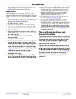
Intersil Corporation reserves the right to make changes in circuit design, software and/or specifications at any time without notice. Accordingly, the reader is
cautioned to verify that the Application Note or Technical Brief is current before proceeding.
For information regarding Intersil Corporation and its products, see www.intersil.com
UG003.0
September 17, 2014
Submit Document Feedback
FIGURE 29. THERMAL IMAGE AT V
IN
= 12V, V
OUT
= 1V, I
OUT
= 50A,
f
SW
= 300kHz, T
A
= +25°C, NO AIRFLOW
FIGURE 30. THERMAL IMAGE AT V
IN
= 14V, V
OUT
= 5V, I
OUT
= 50A,
f
SW
= 533kHz, T
A
= +25°C, NO AIRFLOW
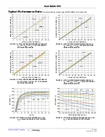
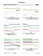
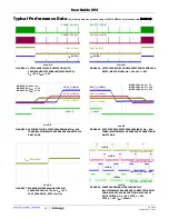
Typical Performance Data
The following data was acquired using a ISL8272MEVAL1Z evaluation board. (Continued)


