background image

10

90USA - CONNeCTINg The fACe MASk

1.

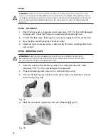
  Connect the breathing valve to the mask by pushing the valve into the  

connection piece and turning it counter clockwise until the bayonet coupling is 

locked. [Fig. 13] 


Fig. 13

aTTenTIOn! 

WHEn PUSHInG THE BREATHInG VALVE In PLACE, THE FInGERS SHALL nOT BE POSITIOnEd On 

THE InTERnAL SPEECH dIAPHRAGM SInCE THIS CAn dAMAGE IT.

2.

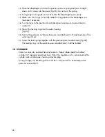
  Mount the external speech cone in the face mask. Tighten the hand screws by 

hand. [Fig. 14] 


Fig. 14

90USA - DISCONNeCTINg The fACe MASk

1.  

Loosen the two hand screws and remove the external speech cone.

2.  

Turn the breathing valve clockwise until it disengages from the bayonet coupling 

and pull away from the mask.

Summary of Contents for 90USA

Page 1: ...user manual 90USA and 90USA S 30249A01...

Page 2: ...to misuse improper maintenance or negligence II altered or repaired in any way that has in INTERSPIRO s judgement adversely affected its performance or reliability III used in an application or for a...

Page 3: ...atory protection during entry into or escape from oxygen deficient atmospheres gases and vapors at temperatures above 25 degrees F 32 degrees C Approved only when compressed air reservoir is fully cha...

Page 4: ...to users instructions before donning ACCESSORIES ALTERNATE CYLINDER ASSEMBLY ALTERNATE AIRLINE HOSES SPIROHATCH SPECTACLE KIT RADIO ATTACHMENT VPU SPIRONET SPIROPASS SPECTACLE KIT SPECTACLE KIT Savox...

Page 5: ...onnecting and disconnecting the face mask 9 5 apparatus pre use check 11 6 donning 12 7 check before use 13 8 remove the apparatus 14 9 clean and disinfect 14 10 storage 18 11 Extra Air Connection 19...

Page 6: ...tos may require other actions than described in this manual The guarantees and warranties specified in the conditions of sale are not extended by this Safety Notice The compressed air with which the c...

Page 7: ...nder valve hand tight to the cylinder connection of the manifold block Fig 2 Fig 2 3 Tighten the cylinder strap by pulling the free end Do not over tighten Fig 3 If the strap is over tightened the buc...

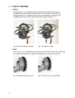
Page 8: ...ltaneously press down the indicator arm and push the exhalation valve cover away from the face mask Fig 6 and Fig 7 Fig 6 Activated positive pressure Fig 7 Ambient air mode 90USA Positive pressure is...

Page 9: ...ushing the breathing valve in place the fingers shall not be positioned on the internal speech diaphragm since this can damage it 2 Connect the breathing valve to the breathing hose Fig 12 NOTE Some 9...

Page 10: ...the breathing valve in place the fingers shall not be positioned on the internal speech diaphragm since this can damage it 2 Mount the external speech cone in the face mask Tighten the hand screws by...

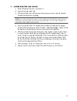
Page 11: ...e gauge should not move during one minute If it does indicating leakage repairs should be made by an authorized service personnel and the test repeated 5 With the cylinder closed open the by pass valv...

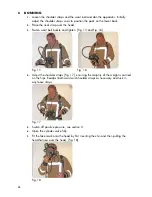
Page 12: ...and tighten Fig 15 and Fig 16 Fig 15 Fig 16 4 Adjust the shoulder straps Fig 17 ensuring the majority of the weight is carried on the hips Readjust both waist and shoulder straps as necessary and tuck...

Page 13: ...tive pressure activates automatically 7 CHECK BEFORE USE 1 Hold your breath and listen for leakage adjust the face mask if necessary 2 Check that a strong air flow is heard when two fingers are insert...

Page 14: ...23 Fig 22 Fig 23 9 Clean and disinfect 1 Open the cylinder valve and check that there is pressure in the system before cleaning Note Having the cylinder valve open prevents water from entering the sy...

Page 15: ...the mask to remove excess water and dry the mask avoiding direct heat and sunlight In certain circumstances it is necessary to disassemble part of the mask in order to clean it Instructions for Extend...

Page 16: ...tions supplied with the disinfectant 3 Rinse the face mask thoroughly with clean water 4 Shake the mask to remove excess water and dry the mask avoiding direct heat and sunlight 90USA breathing valve...

Page 17: ...er maximum 104 F with a mild detergent to remove dirt Check that there are no remnants of dried body fluids 9 Disinfect following the instructions supplied with the disinfectant 10 Rinse thoroughly wi...

Page 18: ...locking ring onto the valve housing Fig 24 20 Centre the guide pin on the positive pressure attachment in the oblong hole of the valve insert lever 21 Screw the locking ring together with the positiv...

Page 19: ...female coupling with a non return valve opener is used This device opens the non return valve in the male coupling mechanically This female coupling must not be used in airline systems as the non ret...

Page 20: ...scribed in the Service and Testing Schedule with publication number 97307 Local requirements may differ due to regulations and environmental conditions In case of doubt consult your local INTERSPIRO r...

Page 21: ......

Page 22: ...LES DIVISION www interspiro com 305 305A Lorong Perak Taman Melawati 53100 KUALA LUMPUR MALAYSIA TEL 60 3 4105 8122 FAX 60 3 4105 3122 E MAIL asiapacific interspiro com CENTRAL EUROPE AUSTRIA INTERSPI...

Reviews: