31
Table 10
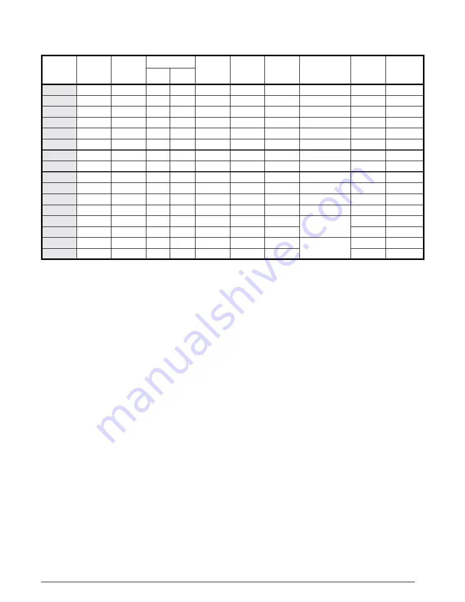
Table 10. M1/M5 Furnace specifications - Factory settings
FuRnacE
MoDEl #
InPut
MBtu/H
outPut
MBtu/H
oRIFIcE no
E.s.P.
IN WC
OIL
noZZlE
IGnItoR
DIREct
COMB.
BloWER
MotoR
HP
a/c REaDY
TONS
NAT.
lP
M1MB 056
56
46
29
45
0.3
x
x
1/4
3
M1MC 056
56
46
29
45
0.3
x
x
1/2
4
M1MB 070
70
57
24
42
0.3
x
x
1/4
3
M1MC 070
70
57
24
42
0.3
x
x
1/2
4
M1MB 077
77
62
21
40
0.3
x
x
1/4
3
M1MC 077
77
62
21
40
0.3
x
x
1/2
4
M1MB 090
90
72
17
36
0.3
x
x
1/4
3
M1MC 090
90
72
17
36
0.3
x
x
1/2
4
M1BB 066
66
53
26
43
0.3
x
x
1/4
3
M1BC 066
66
53
26
43
0.3
x
x
1/2
4
M1BB 086
86
68
18
37
0.3
x
x
1/4
3
M1BC 086
86
68
18
37
0.3
x
x
1/2
4
M5SB 066
66
56
0.3
.50 Gph
x
Burner Model:
AF-10
1/4
3
M5SC 066
66
56
0.3
.50 Gph
x
1/2
4
M5SB 086
86
73
0.3
.65 Gph
x
Spray Angle:
80° A
1/4
3
M5SC 086
86
73
0.3
.65 Gph
x
1/2
4
notEs:
• Electrical Supply - 120 volts, 60HZ, 1 Ph. Fuse or Breaker - 15 amps
• Temperature Rise - 45° F to 75° F
• High Altitude - See
. For Canadian Altitudes
(2,000’ to 4,500’), reduce the gas manifold pressure to 3.0”
W.C.
for natural gas and to 8” W.C. for LP gas.
• Thermostat Circuit - 24 volts, 60HZ, 30 vac
• Normal Anticipator Setting - 0.4
• Manifold Pressure -
Natural Gas: 3.5” w.c.
LP Gas: 10” w.c.
FIGuREs & taBlEs


