14
Line Voltage Wiring
WaRnInG:
to avoid electric shock, personal injury, or death,
turn off the electric power at the disconnect or the
main service panel before making any electrical
connections.
• Electrical connections must be in compliance with all
applicable local codes with the current revision of the
National Electric Code (ANSI/NFPA 70).
• For Canadian installations the electrical connections
and grounding shall comply with the current Canadian
Electrical Code (CSA C22.1 and/or local codes).
It is recommended that 115VAC line voltage be supplied
to the furnace from a dedicated branch circuit containing
the correct fuse or circuit breaker for the furnace as listed
in Table 6, (page 16).
IMPoRtant notE:
Refer to the wiring diagram inside the control box
cover or
for the wiring of your particular unit. any other wiring
methods must be acceptable to authority having
jurisdiction.
cautIon:
label all wires prior to disconnection when
servicing controls. Wiring errors can cause
improper and dangerous operation. Verify proper
operation after servicing.
IMPoRtant notE:
Proper line voltage polarity must be maintained in
order for the control system to operate correctly.
Verify the incoming neutral line is connected to the
white wire and the incoming “hot” line is connected
to the black wire. the furnace will not operate unless
the polarity and ground are properly connected as
shown in
.
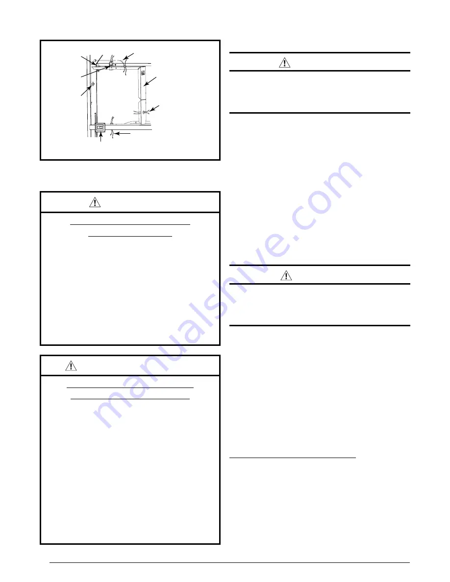
Route all electrical wiring to the left side of the furnace.
See
. For installation of A-size Cabinet furnaces,
allow sufficient slack in the wiring if an optional cooling
coil cabinet is added at a later time.
use of copper
conductors is recommended.
Connecting Power Supply Wires
1. Remove the furnace control panel cover.
2. Route wires (115 VAC) through the strain relief on the
left side of the furnace control box (
3. Connect the
hot
wire to the
black
pigtail lead, and
the
neutral
wire to the
white
pigtail lead. Secure all
connections with suitable wire nuts.
4. Connect the
ground
wire to the grounding screw.
5. Reinstall the control panel cover and secure with the
original mounting screws.
Figure 24
Figure 24. control Panel (all Models)
On-Off
Switch
Blower
Plug
Power
Entry
On-Auto Switch
(Heating Models Only)
Thermostat Wires
Furnace
Control Box
To combustion
Blower or Flame
Roll-out Switch
To Gas Valve
or Burner
ElEctRIcal InFoRMatIon
WaRnInG:
ElEctRIcal sHocK, FIRE oR
EXPlosIon HaZaRD
Failure to follow safety warnings exactly could
result in serious injury or property damage.
Improper servicing could result in dangerous
operation, serious injury, death or property
damage.
• Before servicing, disconnect all electrical
power to furnace.
• When servicing controls, label all wires prior
to disconnecting. Reconnect wires correctly.
• Verify proper operation after servicing.
aVERtIssEMEnt:
RIsQuE DE cHoc ÉlEctRIQuE,
D’IncEnDIE ou D’EXPlosIon
le non-respect des avertissements de sécurité
pourrait entraîner un fonctionnement dangereux
de l’appareil, des blessures graves, la mort ou
des dommages matériels.
un entretein incorrect pourrait entraîner un
fonctionnement dangereux de l’appareil, des
blessures graves, la mort ou des dommages
matériels
• couper toute alimentation électrique au
générateur d’air chaud avant de prodéder aux
travaux d’entretein.
• au moment de l’entretien des commandes,
étiquetez tous les fils avant de les débrancher.
s’assurer de les raccorder correctement.
• s’assurer que l’appareil fonctionne
adéquatement aprés l’entretien.


