6
INS
TA
LL
ATI
O
N
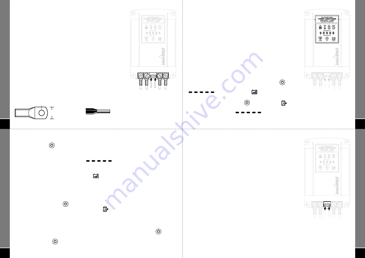
Auxiliary Terminal Block: The auxiliary terminals are optional and not
required for operation of the SPCi, however they do provide some very
useful functions. Please refer to pages 9-10 for details of the specifi c
control and monitoring functions of the auxiliary circuits.
When connecting any of the optional auxiliary circuits (terminal block)
the wiring used is for low power circuits and should be wired according
to the schematic on pages 14-15. For reference purposes the maximum
current for each of the connections is as follows:
• Terminal A: This is the external alarm output connection and is
limited to 250mA @ input voltage i.e. 24VDC nominal.
• Terminal R: This is the remote control input and is signal current
only. Supply is 8-32VDC via a control switch.
When wiring to the auxiliary terminal block it is recommended that
proper boot-lace or ferrule type crimp connectors are used (see below).
The terminating tunnels in the auxiliary terminal blocks are a cage type
and do not need excessive force to make good contact. Do not over-
tighten the terminal screw.
12mm
MAX
5.0-6.0mm
COPPER LUG
BOOT-LACE FERRULE
4.0mm
diameter
MAX
2.0mm
diameter
MAX
INPUT
AUX.
+24V –0V
R
A
+24V
-0V
OUTPUT
INPUT
AUX.
+24V –0V
R
A
+24V
-0V
OUTPUT
8
Step 2 – Changing Output Setting
Press the SET button
again to scroll through the display incrementally to select the desired
setting for your specifi c application as follows:
• For use as a power conditioner the output setting can be adjusted between 24.0V and 28.0V in
1V increments on the OUTPUT VOLTS bar
display. It is important to ensure
the equipment connected to the output of the SPCi is correctly rated for the voltage you have
selected.
• For use as a battery charger the CHARGE icon
must be selected which changes the output
from a continuous DC regulated supply to a special two stage charging protocol (sample curve
data available upon request). The two stages consist of a boost cycle of 28.8V and a fl oat cycle of
27.2V. These voltages are not adjustable.
Step 3 – Saving Output Setting
Simply release the SET button
at the desired point and the output will adjust automatically to
the new setting after a few moments. The OUTPUT icon
will pulse rapidly and then disappear
indicating the setting has been successfully saved.
The new setting will be displayed for a further 10 seconds as confi rmation of the new setting. The
selected setting will now be permanently memorised but can be changed at any time if necessary.
NOTE:
The factory default settings can be reset at any time. Press and hold the SET button
for 30 seconds until all icons on the operator interface display are illuminated (pulsing).
Release the SET button
and the factory default settings will be restored at which point the
illuminated icons will disappear.
OP
ER
AT
ION
7
OP
ER
AT
ION
OPERATION
INITIAL SET-UP
One of the major features of the Gen II SPCi is the ability to adjust
the output voltage when used as a conditioner or alternatively,
select a two stage voltage curve when used as a battery charger
(lead acid only).
As detailed in the wiring section, the output voltage of the SPCi
should ideally be selected before connecting the output supply
to the 24V equipment or battery. The SPCi output can however,
be adjusted at any time providing there is power on the input and
NO load on the output.
The output voltage cannot be adjusted in battery charging mode.
IMPORTANT: A battery should only be connected to the SPCi in
battery charging mode and NOT in power conditioner mode.
Step 1 – Enter Output Set-Up Mode
To adjust the output voltage press and hold the SET button
for 5 seconds until the 5 bars of the OUTPUT VOLTS indicator
and the CHARGE icon
are illuminated
intermittently (fl ashing).
At this point release the SET button
. The OUTPUT icon
and the factory default voltage setting of 26.0V is displayed on
the OUTPUT VOLTS indicator
.
INPUT
AUX.
+24V –0V
R
A
+24V
-0V
OUTPUT
INPUT
AUX.
+24V –0V
R
A
+24V
-0V
OUTPUT
9
OP
ER
AT
ION
EXTENDED FEATURES
The GEN II SPCi has a range of optional features which can be
utilised for control and monitoring purposes.
These functions are enabled through the use of the auxiliary
terminal connections. This is a Euro style terminal block located
between the input and output terminals of the SPCi.
The Euro style terminal block is a high quality two pole connector
used to terminate separate remote monitoring and control or
auxiliary functions. There are no ferrous components in the
terminal block so there is much less risk of corrosion which results
in poor contact.
Please refer pages 14-15 for schematics of the various wiring
circuits available.
External Alarm Output
This output (terminal A) is used for remote monitoring of the pre-
emptive and shutdown alarms of the SPCi. Subsequently any alarm
condition displayed on the operator interface display of the SPCi can
also be remotely monitored i.e. cooling fan fault, unit overheating,
low input voltage, output overload or short circuit.
Generally the output would be connected to a remote sounder/indicator but can also be used to activate a
relay coil to switch a larger warning device. It is important to note that the maximum power of the Alarm
output is limited to 250mA @ input voltage i.e. 24VDC nominal.
INPUT
AUX.
+24V –0V
R
A
+24V
-0V
OUTPUT
INPUT
AUX.
+24V –0V
R
A
+24V
-0V
OUTPUT


