


14
H
EA
D
IN
G
SCHE
M
AT
IC
S
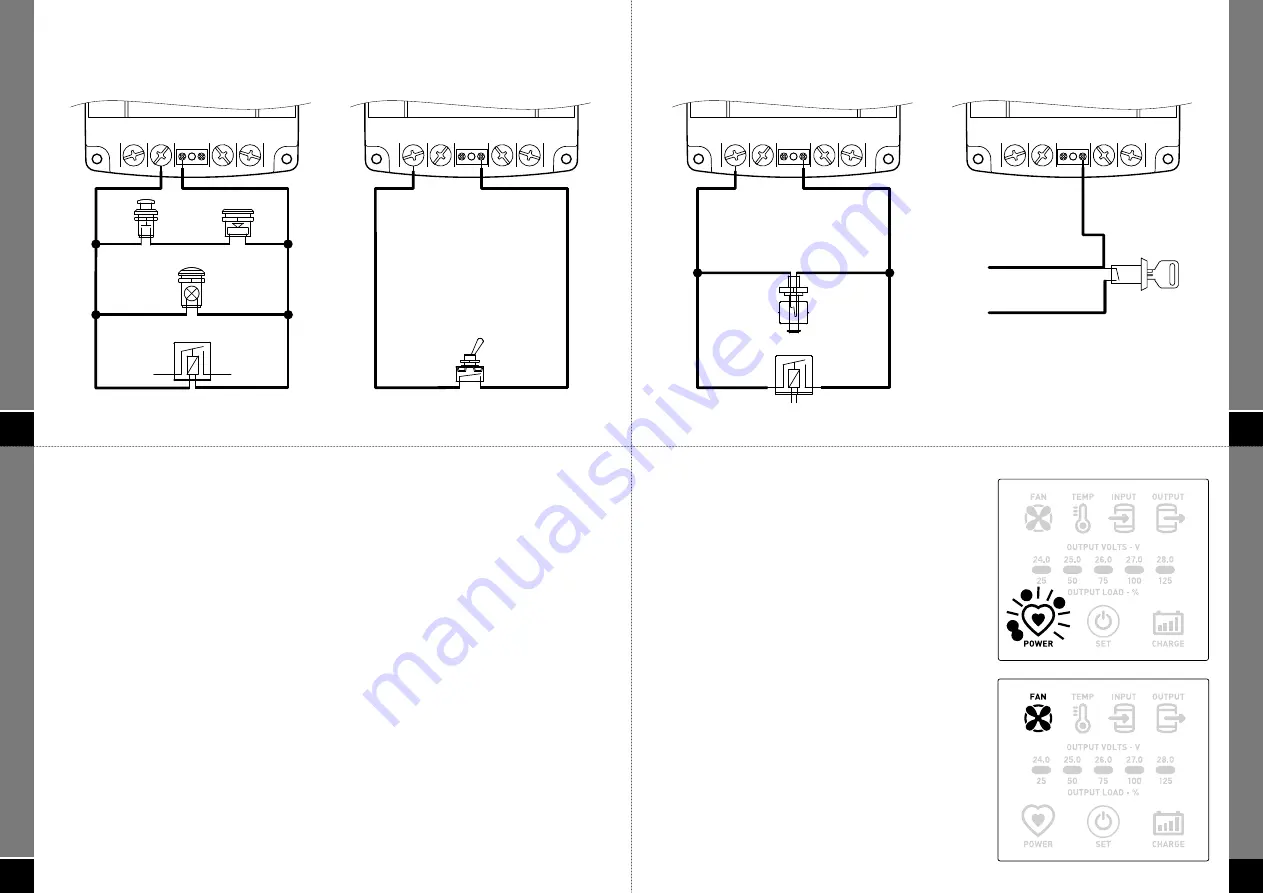
AUXILIARY
External Alarm Output
AUXILIARY
Remote Switching – manual control
INPUT
AUX.
+24V –0V
R
A
+24V
-0V
OUTPUT
RELAY
INDICATOR
BUZZER
MUTE SWITCH
(OPTIONAL)
INPUT
AUX.
+24V –0V
R
A
+24V
-0V
OUTPUT
OUTPUT REMOTE SWITCH
16
O
PER
AT
O
R
IN
TER
FA
CE
INTRODUCTION
The operator interface panel is a new and innovative introduction to the second generation SPCi Maxi
series. This component allows specifi c control functions to aid the installer/operator in addition to
monitoring the status of the unit. The specifi c functions of the operator interface are as follows:
• User selectable voltage output from 24.0V to 28.0V in 1.0V increments to allow for voltage sensitive
equipment or voltage drop over long distances. This is factory set to 26.0V but can be changed at any
time and permanently saved in a non-volatile memory.
• A separate output function which can be selected for charging an auxiliary 24V battery connected
to the output. This automatic 2 stage curve features boost and fl oat modes to reliably maintain a
standard lead acid battery.
• A unique output load indicator which displays the load connected to the output (including overload) in
percentage terms. This indicator is a valuable tool and can be displayed at any time at the push of a
button.
• Useful pre-emptive warning of various fault conditions such as overload, over temperature, low input
voltage and low output voltage (battery charging mode only) prior to shutdown. These alarm functions
can be output for remote monitoring.
• Shutdown protection for critical fault conditions such as overload, over temperature, low input
voltage, fan failure and short circuit of output. These alarm functions can be output for remote
monitoring.
• Resetting of factory defaults at the push of a button.
15
H
EA
D
IN
G
SCHE
M
AT
IC
S
AUXILIARY
Remote Switching –
automatic control
AUXILIARY
Remote Switching – with
ignition switch control
INPUT
AUX.
+24V –0V
R
A
+24V
-0V
OUTPUT
RELAY
FLOAT SWITCH
+ TO IGNITION
+ IGNITION SWITCH SUPPLY
INPUT
AUX.
+24V –0V
R
A
+24V
-0V
OUTPUT
17
O
PER
AT
O
R
IN
TER
FA
CE
POWER ICON
The POWER indicator icon (heart) is illuminated
intermittently (pulsing green) under normal operating
conditions. No other icons or indicators illuminate in this
mode if there are no fault conditions. If a remote control
switch is connected it must be in the ‘on’ position for the
POWER icon to indicate.
FAN ICON
The FAN indicator icon displays a fault condition in relation
to the internal cooling fan of the SPCi. In this condition
the FAN icon is illuminated continuously (steady red) and
the alarm output is activated (to external warning device
if connected). The SPCi will continue to operate in this
condition providing the temperature does not escalate
to shutdown mode. The alarm condition is self-resetting
should the fault condition revert to normal. Cooling
fan failure can be as a result of burn-out, obstruction,
disconnection, etc (see troubleshooting guide)


