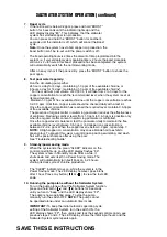
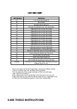
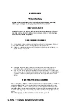
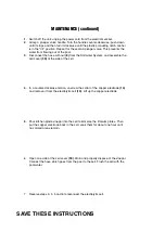
background image

SAVE THESE INSTRUCTIONS

Page 13

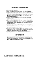
Strainer & Plunger Valve Setup (large 

SPs

)

The strainer grid prevents large objects from jamming and/or damaging the

filter pump. The plunger valve assembly prevents water from flowing into the

filter pump while the filter cartridge is being placed or cleaned. If your pool

has an inflatable top ring, install the strainer, nozzle and plunger valve before

inflating the pool liner top ring. The parts numbers here onward, refer to the

parts depicted in the Parts List section of this manual. To install, do the 

following:

STRAINER & PLUNGER VALVE SETUP (continued)

1.

Grasp the strainer and plunger valve

mechanism.

2.

In a counter-clockwise motion unscrew

plunger valve union from the threaded

strainer connector 

(24) (see drawing 1).

Be careful not to lose the step rubber

washer 

(21)

. Place the plunger valve on

the ground in a safe place.

3.

In a counter-clockwise motion unscrew the

strainer nut 

(22) 

from the threaded

connector 

(24).

Leave the flat washer 

(23)

on the connector 

(24)

.

4.

Install the strainer and plunger valve at the

lower position of pool outlet (marked "+").

From the inside of the pool liner insert the

connector 

(24)

into one of the pre-cut holes

with the washer remaining on the

connector to be placed against the inside

of the liner wall.

5.

Before assembly, lubricate the threads with

a petroleum jelly. Then, with the flat side of

the strainer nut 

(22) 

facing the outside wall

of the liner in a clockwise motion screw the

strainer nut 

(22) 

back onto the threaded

connector 

(24) (see drawing 2)

.

6.

Finger tighten the strainer nut 

(22) 

onto the

threaded connector 

(24)

.

7.

Grasp the plunger valve assembly. Make

sure the step washer 

(21)

is in place.

8.

In a clockwise motion screw the plunger

valve union back onto the threaded

connector 

(24) (see drawing 3)

.

9.

Examine the plunger valve to see if the

handle is pushed fully down to the "0/1"

position. If not, grasp the handle at

the top and push down, turning the handle

in a clockwise direction until the plastic

protruding notch anchors in the "0/1"

position. This will prevent water from

flowing out during filling of the pool 

(see

drawings 4.1 & 4.2)

.

Summary of Contents for Krystal Clear Saltwater System

Page 1: ...K OF ELECTRIC SHOCK CONNECT ONLY TO GROUNDING TYPE RECEPTACLE PROTECTED BY A CLASS A GROUND FAULT CIRCUIT INTERRUPTER GFCI CAUTION FOR CONTINUED PROTECTION AGAINST POSSIBLE ELECTRIC SHOCK USE ONLY IDE...

Page 2: ...LED PUMP FP WORKING BOOST 80 SLEEP 93 LOW FLOW 90 LOW SALT 91 HIGH SALT 92 SERVICE Reg No 29925 P C P A EN...

Page 3: ...concentration has reached the required level but not below 0 6ppm of free available chlorine Copper ions level 0 2 0 3 ppm READ THE LABEL AND OPERATING MANUAL BEFORE USING KEEP OUT OF REACH OF CHILDRE...

Page 4: ...TS ACT This cell must only be used on these models of Saltwater System Read the Label the Installation Manual and Operation Manual of the Krystal Clear Saltwater System Model CS8110 before using and o...

Page 5: ...T This cell must only be used on this model of copper ionization device Read the Label the Installation Manual and Operation Manual of the copper ionization device Krystal Clear Saltwater System Filte...

Page 6: ...stance Visit www intexcorp com For technical assistance and missing parts call us toll free for U S and Canadian Residents 1 800 234 6839 Monday through Friday 8 30am to 5 00pm Pacific Time Don t forg...

Page 7: ...ools Cyanuric Acid Table 19 Non Intex Pools Salt Table 20 Non Intex Pools Operating Time Table 20 Non Intex Pools Cyanuric Acid Table 20 Operating Instructions 21 23 LED Code Chart 24 Maintenance 25 2...

Page 8: ...ing on it and accessing the pool Do not operate this product when the pool is occupied Never use the pool if indicated chlorine level is more than 3ppm This product is intended to be used only for the...

Page 9: ...FCI LED PUMP FP WORKING BOOST 80 SLEEP 93 LOW FLOW 90 LOW SALT 91 HIGH SALT 92 SERVICE SAVE THESE INSTRUCTIONS CONTROLS BACTERIA AND ALGAE in Storable Swimming pool Waters 20 67 A Maximum of 40 000 L...

Page 10: ...SAVE THESE INSTRUCTIONS Page 5 PARTS LIST NOTE Drawings for illustration purpose only Actual product may vary Not to scale...

Page 11: ...SAVE THESE INSTRUCTIONS Page 6 PARTS LIST continued NOTE Drawings for illustration purpose only Actual product may vary Not to scale...

Page 12: ...able protection against harmful interference in a residential installation This equipment generates uses and can radiate radio frequency energy and if not installed and used in accordance with the ins...

Page 13: ...E WITH NUTS WATER TRANSFER HOSE WITH COLLAR AND 2 HOSE CLAMPS SCREW FLOW SENSOR O RING A ELECTROLYTIC CELL WITH 2 SCREWS O RING A INCLUDED COPPER ELECTRODE FLOW SENSOR CONDUIT O RING C ANGLE JOINT O R...

Page 14: ...9 NOTE Drawings for illustration purpose only Actual product may vary Not to scale PARTS REFERENCE continued Before assembling your product please take a few minutes to check the contents and become...

Page 15: ...HOSE O RING STEP WASHER INCLUDED HOSE O RING STEP WASHER STRAINER NUT FLAT STRAINER RUBBER WASHER THREADED STRAINER CONNECTOR ADJUSTABLE POOL INLET NOZZLE ADAPTOR B OPTIONAL STRAINER CONNECTOR OPTIONA...

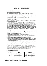
Page 16: ...produce HOCP The HOCP dissolves in the water and instantly starts destroying bacteria and algae It also oxidizes all other organic materials Low voltage direct current is applied to the copper electro...

Page 17: ...e the step washer 21 is in place Connect adaptor B 26 to plunger valve union 4 Repeat steps 1 through 3 for nozzle and plunger valve mechanism 5 Remove wall plug and then insert the strainer 27 29 int...

Page 18: ...eave the flat washer 23 on the connector 24 4 Install the strainer and plunger valve at the lower position of pool outlet marked From the inside of the pool liner insert the connector 24 into one of t...

Page 19: ...ainer nut 22 facing the outside wall of the liner in a clockwise motion screw the strainer nut 22 back onto the threaded connector 24 see drawing 6 6 Finger tighten the adjustable pool inlet nozzle 25...

Page 20: ...1 2 turns to open DO NOT remove air release valves as water will expel with force if the motor is turned on and injury may occur 6 Grasp and remove the filter housing cover 4 Check to see if a cartri...

Page 21: ...hold both and buttons for 5 seconds The LED flashes FP The unit is now in a Filter pump working mode Switch the filter pump on to start the water circulation 2 Keep the saltwater system turned off 3...

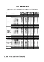
Page 22: ...x 124cm 18 8 x 53 569cm x 135cm 18 x 10 x 42 549cm x 305cm x 107cm 20 x 12 x 48 610cm x 366cm x 122cm 24 x 12 x 48 732cm x 366cm x 122cm 28 x 12 x 48 853cm x 366cm x 122cm 18 x 9 x 52 549cm x 274cm x...

Page 23: ...15 x 36 457cm x 91cm 15 x 42 457cm x 107cm 15 x 48 457cm x 122cm 16 x 48 488cm x 122cm 18 x 48 549cm x 122cm 18 x 52 549cm x 132cm 20 x 52 610cm x 132cm 24 16 x 48 488cm x 122cm 18 x 52 549cm x 132cm...

Page 24: ...x 48 488cm x 122cm 18 x 48 549cm x 122cm 18 x 52 549cm x 132cm 20 x 52 610cm x 132cm 2 24 16 x 48 488cm x 122cm 18 x 52 549cm x 132cm 16 8 x 49 508cm x 124cm 18 8 x 53 569cm x 135cm 18 x 10 x 42 549cm...

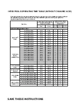
Page 25: ...Water Capacity Liters x 0 003 Water Capacity Gals x 0 0067 Water Capacity Liters x 0 0008 Water Capacity Operating Time hours at different ambient air temperatures Gals Liters 10 19 C 50 66 F 20 28 C...

Page 26: ...e air has escaped water will flow out of the valves 1 7 When this occurs gently finger tighten the valves in a clockwise direction 5 Turn on the switch The filter pump is now filtering the water 6 The...

Page 27: ...many hours The built in timer will now activate your Saltwater System at the same time each day for the number of hours you have set NOTE The Saltwater System will not operate if the filter pump is n...

Page 28: ...pool water reduces the effectiveness of sanitizers Reducing sanitizer levels from 1 3 ppm to 0 6 3 ppm is possible only when the organic matter content in swimming pool water is controlled Once the co...

Page 29: ...ining 12 Maximum Operating Hours 12 hours remaining 90 Alarm Code Low Water Flow No Flow 91 Alarm Code Low Salt Level 92 Alarm Code High Salt Level 93 Stand By Mode Operating Process finished BLANK No...

Page 30: ...h water does not remove the deposits use a plastic brush to clean the surface and the hinge if necessary Do not use a metal brush 4 After the flow sensor has been inspected and cleaned align the locat...

Page 31: ...e Saltwater System and assemble the cell cover 30 at the side of the cell 4 In a counter clockwise motion unscrew the collar of the copper electrode 14 and remove it from the electrolytic cell 13 Lift...

Page 32: ...de of the filter housing 8 If dirt or sediment is located on the bottom of the housing then A In a counter clockwise motion gently unscrew and remove the sediment valve 1 located at the bottom of the...

Page 33: ...and remove immediately 2 Hold the strip level for 15 seconds Do not shake excess water from the strip 3 Now compare the strip pad to the color chart on the packaging label If necessary adjust the che...

Page 34: ...sic a solution is Result if too low Corroded metals eye skin irritation destruction of total alkalinity Result if too high Scale formation cloudy water shorter filter runs eye skin irritation poor Chl...

Page 35: ...ound Fault Circuit Interrupter or RCD Reset circuit breaker If circuit breaker trips repeatedly your electrical system may have a defect Turn off circuit breaker and call an electrician to correct the...

Page 36: ...store I S Remove the cell for inspection clean it if necessary See Maintenance Contact Intex Service Center Drain about 20 of the pool water and add fresh water to decrease the copper ion concentratio...

Page 37: ...ecessary See Set Up Instructions Check that the arrow on the flow sensor conduit points in the same direction as the one on the cell Reverse the flow sensor conduit if necessary Clean the flow sensor...

Page 38: ...about potential pool hazards and about the use of protective devices such as locked doors barriers etc Teach children what to do in case of an emergency Always use common sense and good judgement whe...

Page 39: ...settlement board and unless and until the provisions of these paragraphs are carried forth no civil action may be instituted The methods and procedures of this settlement board shall be subject to the...

Page 40: ...3813 E mail suproadmin supropanama com COSTA RICA CENTURY USA LLC DOMINICAN REPUBLIC 4731 W Atlantic Ave Suite B 3 GUATEMALA Delray Beach FL 33445 USA COLOMBIA Tel 561 495 0648 VENEZUELA Fax 561 495...

Page 41: ...le Rechte vorbehalten Printed in China Imprim en Chine Impreso en China Gedruckt in China Trademarks used in some countries of the world under license from Marques utilis es dans certains pays sous li...

Page 42: ...ormation This service and this information do not replace the official hard copy label The PMRA does not provide any guarantee or assurance that the information obtained through this service is accura...

Reviews: