5
Installation
5.9
Installing the
panels for the fire-protection modules
64
INTILION GmbH
5.9
Installing the panels for the fire-protection modules
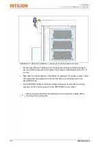
Panels are installed in front of the fire-protection modules, in front of the battery
management system (BMS) and in front of the inverter.
The panels for the ControlShield and the installation areas are installed at a later
date.
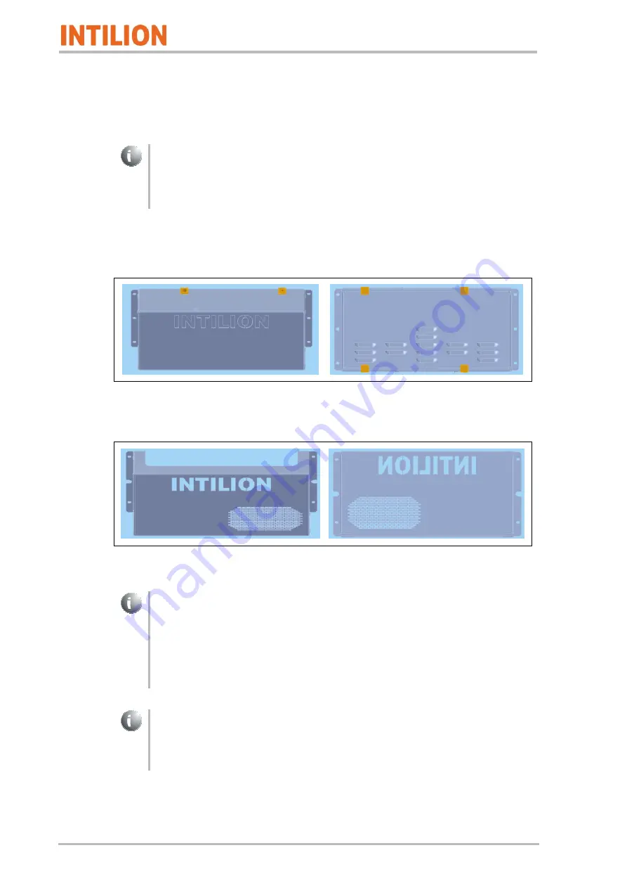
The various panel types are shown below:
Panel for the fire-protection modules
Illustration 25: Panel for the fire-protection modules
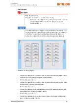
Panel for the battery management system (BMS), the inverter, the ControlShield
and the installation areas
Illustration 26: Panel for the BMS, inverter, the ControlShield and the installation areas
For the fire-protection modules, the panels with louvered metal sheet and Icotek
grommets are used.
For the power cable, the Icotek grommets KT13 are used; for the
communication/ventilator cables, the Icotek grommets KT8 are used.
The procedure for the installation of a panel is described below.
Installation is performed in a similar way for the other panels.
No control cable is connected to battery module 9 (see Section 5.8). In order to
subsequently seal the fire-protection module, there is a dummy grommet (Icotek
grommet with no hole) for the unoccupied recess in the panel. This grommet is
included with the delivery of the INTILION scalebloc.
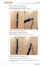
•
Place the Icotek grommets KT13 or KT8 around the corresponding cables.
Summary of Contents for scalebloc 0.5C
Page 33: ...2 Safety 2 10 Obligations of the system manager INTILION scalebloc 0 5C 31 ...
Page 34: ......
Page 46: ...4 Transport and storage 3 3 Technical specifications 44 INTILION GmbH ...
Page 77: ...5 Installation 5 12 Establishing the mains connection INTILION scalebloc 0 5C 75 ...
Page 78: ......
Page 98: ...6 Commissioning 6 8 Contacting the Hoppecke Service team 96 INTILION GmbH ...
Page 100: ......
Page 102: ...8 Fault 100 INTILION GmbH ...


