background image


INTILION scalebloc 0.5C 


93 

6.4 

Filling in the commissioning log 

Carry out additional tasks as per the commissioning log and make a note of the results. 

6.5 


6.6 


Summary of Contents for scalebloc 0.5C

Page 1: ...OPERATING MANUAL original operating manual INTILION scalebloc 0 5C INTILION GmbH Dr Sinsteden Straße 8 D 08056 Zwickau Telephone 49 0 375 270 550 0 Fax 49 0 375 270 550 300 E mail contact intilion com Internet www intilion com Store for future use ...

Page 2: ...ting manual and all of the illustrations contained within are copyright protected Any use that goes beyond the limits of copyright law without the prior written consent of the publisher is impermissible and punishable by law This applies in particular to reproduction translations microfilming storage and processing using electronic systems ...

Page 3: ...s for environmental protection 19 2 5 Special warnings 20 2 5 1 Symbols used on the battery storage system 20 2 5 2 Danger due to electrical energy 21 2 5 3 Dangers due to lithium ion batteries 23 2 5 4 Dangers due to hot surfaces 24 2 5 5 Dangers due to working at height 24 2 5 6 Dangers due to noise 25 2 5 7 Dangers due to the use of incorrect spare parts 25 2 6 Personal protective equipment 25 ...

Page 4: ...mmissioning the energy meter 82 6 3 Settings in the web visualisation 86 6 4 Filling in the commissioning log 93 6 5 Installing the panels for the rest of the components 94 6 6 Contacting the Hoppecke Service team 94 9 1 Safety measures during maintenance work 101 9 2 Inspection and maintenance work 102 9 2 1 Maintenance intervals 102 9 2 2 Preparatory measures 103 9 2 3 Maintenance annual 104 9 2...

Page 5: ...odules 111 10 2 2 6 Disassembling the cables for the lithium ion batteries 112 10 2 2 7 Removing the lithium ion batteries 113 10 2 2 8 Removing the earthing points 114 10 2 2 9 Preparing the battery storage system for loading 115 10 2 2 10 Loading the battery storage system 116 10 3 Disposal 118 ...

Page 6: ...4 Laying the cell connectors 62 Illustration 25 Panel for the fire protection modules 64 Illustration 26 Panel for the BMS inverter the ControlShield and the installation areas 64 Illustration 27 Inserting the Icotek grommets into the panel for the fire protection modules 65 Illustration 28 Securing the panel for the fire protection modules 65 Illustration 29 Icotek frame 67 Illustration 30 Icotek...

Page 7: ... 58 INTILION interface for entering the serial numbers 92 Illustration 59 Securing the panels for the ControlShield and the installation areas 94 Illustration 60 Removing the front panel 109 Illustration 61 Disassembling the panels for the ControlShield and the installation areas 110 Illustration 62 Removing the floor plates 110 Illustration 63 Disassembling the panels for the BMS and the inverter...

Page 8: ...I INTILION GmbH Tables Tab 1 Training 18 Tab 2 Technical specifications battery storage system INTILION scalebloc 0 5C 41 Tab 3 Technical specifications lithium ion batteries 42 Tab 4 Maintenance intervals 102 ...

Page 9: ...e battery storage system This applies in particular to the specified safety instructions After reading the operating manual you will be able to Commission the battery storage system Operate the battery storage system in compliance with the safety standards Properly maintain the battery storage system Properly clean the battery storage system Take appropriate action if an error occurs Decommission ...

Page 10: ...section Structure SIGNAL WORD Symbol providing more details on a hazard Hazard type and source Possible consequence s of non observation Measure s for risk prevention Hazard levels DANGER Hazard with a high level of risk that if not avoided can lead to death or serious bodily injury WARNING Hazard with a medium level of risk that if not avoided can lead to death or serious bodily injury CAUTION Ha...

Page 11: ...1 NOTE without warning triangle see 1 1 1 1 1 3 Other means of representation The information symbol provides useful information These markings are followed by lists These markings are followed by text describing activities that need to be performed in the order in which they are listed Text in quotation marks constitutes references to other chapters or sections 1 1 4 Symbols used in this manual P...

Page 12: ...ery storage system with faulty safety devices or with improperly fitted or non functioning safety and protective equipment Failure to observe the operating manual and the instructions in the operating manual with regard to the installation commissioning operation maintenance and cleaning of the battery storage system Use of non qualified or untrained personnel Structural modifications to the batte...

Page 13: ...d until the discharge end voltage or a State of Charge SoC of 0 is reached whichever comes first with a current rate of 1 3 C 1 C corresponds to current in amperes A which in this case has the same value as the nominal capacity of a cell in ampere hours Ah The battery storage system is left in active standby for 30 minutes The battery storage system must be fully charged using the CCCV Constant Vo...

Page 14: ...TILION GmbH Infringements will lead to liability for damages The right to make any further claims remains reserved 1 5 Service customer service INTILION GmbH is part of the HOPPECKE Group Our customer service team is available to provide you with any technical information you may require HOPPECKE Service Competence Center Tel 49 0 800 246 77 32 German Tel 49 0 180 522 99 99 international Fax 49 0 ...

Page 15: ...y regulations Any existing internal site regulations must also be observed 2 1 Intended use The operational safety of the battery storage system is only guaranteed if it is used as intended The INTILION scalebloc 0 5C is an AC coupled battery storage system and is only suitable for the following application Behind the meter application There are three important features that are worth mentioning f...

Page 16: ...odSG Produktsicherheitsgesetz No modifications additions or conversions may be made to the battery storage system without the prior written approval of INTILION GmbH The product will lose its EU conformity in the event of non compliance The manufacturer of the battery storage system is outside of the warranty and any warranty claims This also applies to welding work on load bearing components Comp...

Page 17: ...ating conditions defined in the data sheet Do not expose the lithium ion cells of the battery storage system to ambient temperatures of above 55 C or below 0 C If you require any more information regarding the permissible operating conditions for the battery storage system cells please contact the HOPPECKE Service team see Section 1 5 Service customer service Do not overcharge or deep discharge th...

Page 18: ...y the operating company or by qualified personnel on the tasks assigned to them and the potential hazards involved with improper conduct as part of a training session Qualified personnel Qualified personnel are those who because of their training knowledge and experience coupled with knowledge of the applicable regulations are in a position to perform the work assigned to them and to independently...

Page 19: ...ery storage system under the supervision of qualified personnel Successfully completed training must be confirmed in writing The operating company is responsible for personnel training 2 2 2 Obligations of personnel All persons assigned with work on the battery storage system are obligated to do the following prior to starting work Observe the basic requirements regarding occupational safety and a...

Page 20: ... protective and safety devices Never take the installed safety devices out of operation If an alarm is triggered the visible warning light and acoustic warning signal continually illuminate sound on the alarm maintain the maximum possible distance from the battery storage system and do not open the battery storage system With indoor battery storage systems leave the room and or building immediatel...

Page 21: ...the location where the battery storage system is used It must be ensured that all persons carrying out work on the battery storage system can access the operating manual at any time 2 4 Safety measures for environmental protection For all work make sure to comply with regulations on waste avoidance and proper waste recycling or disposal During installation and maintenance work in particular as wel...

Page 22: ...be recognised by unauthorised persons Access by persons with medical implants prohibited This symbol warns of electromagnetic fields and the danger to persons with medical implants Some areas of the product generate strong magnetic fields during operation This can impair the functioning of devices such as pacemakers Persons with medical implants must not access the area marked with the warning sig...

Page 23: ...ock e g falls Adhere to the five safety rules when working on the electrical equipment Only ever have work on the electrical equipment performed by a specialised electrician with WLE certification In order to ensure the safe performance of electrical work the operating company can transfer its obligations over to a system manager specialised electrician The transfer of responsibility must be made ...

Page 24: ...y moved This also includes electrical operating equipment that is permanently attached on a temporary basis and that is operated via moving connection cables At least every 6 months have a specialised electrician check the portable electrical operating equipment the connection cables with connectors and the extension and device connection cables together with their connector systems where used Por...

Page 25: ...l packaging or in packaging that corresponds to the applicable guidelines Keep the packagings in a safe place Do not heat up the lithium ion batteries beyond the maximum permissible temperature and do not burn them Make sure that there are no external ignition sources Do not short circuit the lithium ion batteries and do not cause them any mechanical damage do not pierce deform destroy etc When ha...

Page 26: ...r immediately No not induce vomiting Rinse the mouth and surrounding areas with water 2 5 4 Dangers due to hot surfaces Contact with hot components may cause burns Always wear protective work clothing and protective gloves when working near hot components Allow components to cool down to ambient temperature before working on the battery storage system 2 5 5 Dangers due to working at height When wo...

Page 27: ...tery storage system in order to keep health risks to a minimum Always wear the necessary protective equipment when performing work Do not wear any metallic watches rings chains or other jewellery The symbols have the following meanings Protective work clothing isolating protective clothing Protective work clothing is closely fitting work clothing with a low tear resistance with narrow sleeves and ...

Page 28: ...gainst thermal impacts such as arcs and to protect against dangerous electric shock when touching live parts in accordance with DIN EN 50365 Face protection electrician s face protection Wear face protection to protect the eyes and face Wear electrician s face protection suitable for working on live equipment WLE to protect against potential electric arcs Hearing protection Wear hearing protection...

Page 29: ...s been secured against re activation Check all of the safety devices on the battery storage system for correct functioning on a regular basis 2 8 Information regarding emergencies Preventative measures Always be prepared for accidents or fire Keep first aid equipment first aid kit blankets etc to hand Make sure that you are familiar with the accident reporting first aid fire extinguishing and resc...

Page 30: ...y allow people to work on the battery storage system who have reached the statutory minimum age limit The operating company must only allow people to work on the battery storage system who have the appropriate qualifications and training The operating company must ensure that all employees who work with the battery storage system have read and understood the operating manual It must also provide e...

Page 31: ... operating company INTILION scalebloc 0 5C 29 The operating company must perform regular checks to establish that all of the safety instructions and warnings attached to the battery storage system are legible and permanently affixed ...

Page 32: ...m manager is responsible for the safe performance of electrical work The transfer of responsibility is performed in writing by the operating company The system manager must have read and understand the operating manual He or she must consult the HOPPECKE Service Competence Center in the event of misunderstandings ...

Page 33: ...2 Safety 2 10 Obligations of the system manager INTILION scalebloc 0 5C 31 ...

Page 34: ......

Page 35: ... and control of internally connected components One field of application is the behind the meter application which is used to improve the private consumption of locally generated energy or to reduce load peaks in industrial environments but also for pre load storage with regard to electromobility infrastructure The battery storage system can also be used in a wide range of off grid applications wh...

Page 36: ... storage system 3 2 Overview 34 INTILION GmbH 3 2 Overview 3 2 1 Overview of functional elements View with closed door Illustration 1 Functional elements view with closed door 1 LTE antenna 3 Door 2 AC unit 4 Outdoor housing IP55 ...

Page 37: ... Overview INTILION scalebloc 0 5C 35 View with open door Illustration 2 Functional elements view with open door 1 Lithium ion battery 5 Battery management system BMS 2 Socket 6 Inverter 3 Installation area 7 ControlShield 4 Temperature sensor PT1000 ...

Page 38: ...afety devices Illustration 3 Safety devices 1 Visual and acoustic alarm 4 Smoke degasification duct see 3 2 4 6 Smoke degasification duct 2 Smoke detector 5 Door contact switch 3 Fire protection module 6 ControlShield EMERGENCY STOP CONTACTS option of integration into the emergency stop circuit ...

Page 39: ...tachment location The following illustration shows an example type plate Product INTILON scalebloc 0 5C Operation voltage 3 x 400 V 50 Hz Version 1 0 Network configuration TN S Type INP46 175 127 198S E 20 40 90 Rated current max 50 A Weight 950 kg Installed power 30 kVA Dimension W D H 1618 1026 2030 mm Installed capacity 68 5 kWh Material number 0123456789 Serial number 123456789123456789 Constr...

Page 40: ...te 3 2 4 2 Door contact switch Illustration 7 Door contact switch The door contact switch monitors the doors of the battery storage system The AC unit will switch off if the doors are opened If the doors stay open for more than 30 minutes the system will shut down This status is signalled by the alarm the signal horn will repeatedly sound briefly and the signal light will repeatedly illuminate bri...

Page 41: ...r is triggered By contrast if the doors are open the acoustic signal takes the form of a repeated brief tone 3 2 4 4 Emergency stop contacts There are connection terminals on the ControlShield for the integration of an emergency stop switch or an emergency stop safety circuit If this circuit is interrupted the battery storage system will be disconnected from the network by an integrated circuit br...

Page 42: ...egasification duct is intended for the indoor version Always consult INTILION GmbH before performing indoor installation WARNING Risk of injury The targeted removal of smoke gases by the smoke degasification duct is mandatory when the battery storage system is installed inside buildings A pipe should be guided to the outside via the degasification opening underneath the AC unit Contact your instal...

Page 43: ... Energy content usable 61 6 kWh Voltage nominal 728 6 V Current rate max 0 5 C Mains connection 400 V 3 phase Power max 30 kW Dimensions W x H x D approx 1618 mm x 2030 mm x 1026 mm Weight approx 950 kg Housing Outdoor housing IP55 Airborne sound emissions A weighted emission sound pressure level LpA 73 dB A Ambient conditions at the installation site Ambient temperature during operation permissib...

Page 44: ...ltage range 633 6 V 821 7 V C rate max 1 C constant Efficiency 98 Weight 486 kg 9 modules at 54 kg each Battery module Samsung SDI Cell arrangement 22S1P Energy content nominal 7 61 kWh Capacity nominal 94 Ah Voltage nominal 81 V Voltage range 70 4 V 91 3 V Weight 54 kg Dimensions W x H x D 370 mm x 160 mm x 650 mm Cell Samsung SDI Energy content nominal 0 346 kWh Capacity nominal 94 Ah Voltage no...

Page 45: ...ransport company For information on changing the location of the battery storage system please contact INTILION GmbH and observe the following information Lithium ion batteries Only transport and store the lithium ion batteries in their original packaging or in packaging that corresponds to the applicable guidelines Symbols on the packaging must be observed The lithium ion batteries must not be re...

Page 46: ...4 Transport and storage 3 3 Technical specifications 44 INTILION GmbH ...

Page 47: ... without fail For information on changing the location of the battery storage system please contact INTILION GmbH Unless specified otherwise the transport conditions from Section 4 Transport and storage apply 5 1 Information regarding hazards during installation Installation must only be performed by appropriately trained and qualified personnel and in compliance with all of the safety instruction...

Page 48: ... Use collision protection e g bollards protective edges or similar to protect the battery storage system if installation is being performed in an urban area or in a location where there are other moving vehicles Ensure a minimum distances of 1300 mm here We recommend securing the battery storage against unauthorised access touching e g by means of a fence WARNING Risk of injury due to lack of spac...

Page 49: ...owing illustration example illustration Illustration 10 Maintenance areas Requirements for the floor area WARNING Loss of stability A loss of stability can lead to a significant risk of injury The floor area must be even The foundation must have a load bearing capacity of at least 1 t m The operating company is responsible for the static properties of the foundation Please contact INTILION GmbH or...

Page 50: ...he specifications The connections on the AC distribution side have been prepared The necessary installation tools are available 5 4 Disassembling the transport pallet The battery storage system is delivered on a transport pallet The fixing screws must be removed prior to unloading Illustration 11 Disassembling the transport pallet removing the fixing screws Remove the fixing screw 1 at each corner...

Page 51: ... scalebloc 0 5C 49 Illustration 12 Disassembling the transport pallet removing the floor plates If present remove the floor plates 1 to 5 There are two floor plates 1 and 2 on the AC unit side There are three floor plates 3 to 5 on the opposite side to the AC unit ...

Page 52: ... storage system onto the foundation and securing in place The following illustration shows the technical drawing of the base This drawing can be used to ascertain the drill measurements for the attachment of the anchors slots A base template can be requested from INTILION GmbH to help with assembly Illustration 13 Technical drawing of the base ...

Page 53: ...ave an addition person to secure the transport route Keep the working area neat tidy and free of trip hazards Make sure that there are no persons in the path of travel or underneath suspended loads Do not use pipelines or attachment parts as attachment points Only lift the battery storage system at the designated points Always lift the battery storage system slowly and carefully in order to ensure...

Page 54: ... points The attachment points are located on the top of the battery storage system underneath the covers Illustration 14 Overview of the attachment points 1 Attachment points 4 points Illustration 15 Removing the covers over the attachment points If present remove the covers over the attachment points 1 and attach the shackle or hook ...

Page 55: ...n the path of travel or underneath suspended loads Always lift the battery storage system slowly and carefully in order to ensure safety and stability Guide the battery storage system through a rope in order to prevent swinging or twisting Only lift the battery storage system if this can be performed safely given the external conditions e g wind Lift the battery storage system off the transport pa...

Page 56: ...thing system The foundation earthing system designated earthing point in the foundation should be secured from the inside at position 1 on the battery storage system Illustration 17 Securing the earthing system for rack rails Secure the earthing system for the rack rails at position 1 To do so pull the earthing cable through the opening in the floor plate ...

Page 57: ...afety boots and a safety helmet Observe the documentation from the supplier CAUTION Risk of injury due to incorrect lifting and insertion of the lithium ion batteries Incorrect lifting and insertion of the lithium ion batteries leads to ergonomic hazards Proceed as follows when lifting and carrying the lithium ion batteries Position your body as close to the load as possible and make sure to stand...

Page 58: ...the packagings and the lithium ion batteries for damage Only ever insert undamaged lithium ion batteries Contact the HOPPECKE Service team if the packagings or the lithium ion batteries are damaged Illustration 18 Lithium ion batteries delivery condition The lithium ion batteries are delivered in individual boxes Each lithium ion battery is protected by dampening cardboard and a film Illustration ...

Page 59: ...on 20 Lithium ion batteries removing from the box Lift the lithium ion battery out of the box at the gripping points 1 Make sure that the protective caps are fitted on the poles of the lithium ion batteries Also make sure not to touch the poles Slide the lithium ion batteries into the fire protection modules WARNING Danger due to falling lithium ion batteries When carrying the lithium ion batterie...

Page 60: ...crews to a tightening torque of 5 1 to 6 1 Nm Note down the serial numbers of the lithium ion batteries The serial numbers consist of 16 digits and are located on the front of the lithium ion batteries and on the associated boxes Inform INTILION GmbH of the serial numbers these are required for monitoring purposes and for service support via the HOPPECKE cloud solution Start by inserting all lithi...

Page 61: ...valid training by INTILION GmbH Wear arc proof work clothing 1000V protective gloves safety boots and a safety helmet with visor to protect against arcs The visor must be kept closed at all times when carrying out subsequent work Use only insulated tools Place at least one 1 5 m x 1 5 m rubber mat in front of the battery storage system The enclosed wiring diagram shows the wiring of the lithium io...

Page 62: ...Follow the sequence described below when wiring up the lithium ion batteries and when connecting them to the battery management system BMS NOTE Before every installation step make sure to only remove the safety caps for the lithium ion batteries specified in the relevant instruction step This includes the specified poles Otherwise the exposed poles of the lithium ion batteries that are not specifi...

Page 63: ... and are located between the lithium ion battery housings and the roof of the battery storage system top end Illustration 23 Wiring diagram Connect the cable with the marking shown in yellow in the diagram bottom end to connection B on the battery management system BMS Put the safety caps back on Connect the cable with the marking shown in yellow in the diagram top end to the positive pole of batt...

Page 64: ...ule 2 to the negative pole of battery module 3 Put the safety caps back on Use the 560 mm long cell connector to connect the positive pole of battery module 4 to the negative pole of battery module 5 Put the safety caps back on Use the 560 mm long cell connector to connect the positive pole of battery module 5 to the negative pole of battery module 6 Put the safety caps back on Use the 560 mm long...

Page 65: ...nnect the BMS connection FAN PWR OUT to battery module 1 connection FAN WR left Use the 300 mm long control cable to connect battery module 1 connections COMM OUT and FAN PWR right to battery module 2 connections COMM IN and FAN PWR left Use the 300 mm long control cable to connect the remaining battery modules to one another in accordance with the previous instruction No control cable is connecte...

Page 66: ... areas Illustration 26 Panel for the BMS inverter the ControlShield and the installation areas For the fire protection modules the panels with louvered metal sheet and Icotek grommets are used For the power cable the Icotek grommets KT13 are used for the communication ventilator cables the Icotek grommets KT8 are used The procedure for the installation of a panel is described below Installation is...

Page 67: ...s Insert the Icotek grommets 1 into the recesses on the panel Make sure that the Icotek grommets are correctly positioned The flat side of the Icotek grommets must be pressing against the fire protection module Illustration 28 Securing the panel for the fire protection modules Attach the panel to the fire protection module with six screws 1 Tighten the screws to a tightening torque of 5 Nm ...

Page 68: ...5 Installation 5 9 Installing the panels for the fire protection modules 66 INTILION GmbH Make sure that the panel is flush This is essential for the correct functioning of the fire protection concept ...

Page 69: ...the Icotek frame in their almost final position not yet connected see following illustration Illustration 29 Icotek frame 1 Icotek frame 2 Grommets In order to guarantee that the battery storage system has IP 55 protection the cables need to have the Icotek frame and the correct Icotek grommet Disassemble the Icotek frame from the floor plate Place the suitable Icotek grommets around the correspon...

Page 70: ...at closes when pressure is applied Illustration 30 Icotek grommet suitable for cable Illustration showing an unsuitable Icotek grommet The Icotek grommet is far too small and does not fit around the cable Illustration 31 Icotek grommet not suitable for cable Thread the cable with Icotek grommet into the Icotek frame When doing so make sure that the flat sides of the Icotek grommets are resting aga...

Page 71: ... though 5 11 Final measures Illustration 32 Securing the front panel Insert the side panels and push them backwards to the back of the battery storage system Insert the front panel and push it as far as it will go approx 10 mm in the direction of the arrow Secure the front panel using the previously removed enclosed screws 1 Carry out a visual inspection In particular check whether there are any t...

Page 72: ...oor to the AC unit door can be opened by a maximum of 90 Adjust the setpoints to 23 C for Controls Condenser Blower Compressor 1 and to 16 C for Controls Heater 2 The following illustrations show the positions of the adjustment elements in the AC unit Illustration 33 Adjusting the AC unit 2 3 C 1 6 C ...

Page 73: ...pply company must be complied with when establishing the mains connection The battery storage system has a power output of 30 kVA per outdoor control cabinet The power cable must be set up based on the power output as well as the cable length and the ambient conditions in accordance with VDE 0100 A power cable with the dimensions 5 x 16 mm is recommended The maximum core cross section that can be ...

Page 74: ...ly and possibly also the total feed from the customer s system Illustration 35 Energy meter connection diagram INTILION GmbH offers a range of different energy meters and transformers for more information please contact either your contact partner or the HOPPECKE Service team The energy meter communicates with the battery storage system via a network cable This should meet at least category 5 Cat ...

Page 75: ...In this case each battery storage system must be connected to the low voltage distribution with a separate connecting cable Communication between the battery storage systems is performed via the Master Slave system With the master system the energy meter is connected as previously described Communication between the battery storage systems is performed via a network cable min Cat 5 A schematic rep...

Page 76: ...bH Illustration 38 Ethernet ports for connecting the energy meter and the battery storage system Either the previous battery storage system or the energy meter in the event of the Master is connected to port XF14 The next battery storage system is connected to port XF15 ...

Page 77: ...5 Installation 5 12 Establishing the mains connection INTILION scalebloc 0 5C 75 ...

Page 78: ......

Page 79: ...see Section 1 5 Service customer service WARNING Risk of injury due to lack of space When commissioning the battery storage system there is a risk of injury such as scratches puncture wounds or fractures as a result of an excessively close arrangement of the necessary work equipment and or components Cordon off the danger zone Keep unauthorised persons away from the area Appoint a responsible pers...

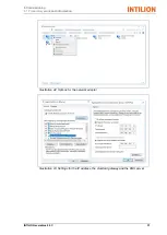
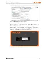
Page 80: ...e performed during the course of commissioning require you to change the network address of your commissioning computer laptop This description is aimed at Windows 10 users but is also applicable to Windows 7 The control panel which is accessed either via the gear symbol on the left hand side of the Start menu or by typing control panel after pressing the Windows button can be seen in Illustration...

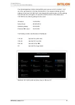
Page 81: ...rea all of the settings here will need to be changed too If you wish to reach a device in the address area 192 168 55 X the following settings must be used IP address 192 168 55 2 Subnet mask 255 255 255 0 Standard gateway 192 168 55 1 Preferred DNS server 192 168 55 1 The following numbers are blocked as IP addresses 10 to 29 reserved for control units 30 to 49 reserved for converters 50 to 69 re...

Page 82: ...6 Commissioning 6 1 Preparatory work and information 80 INTILION GmbH Illustration 40 Network and Internet section of the control panel Illustration 41 Network adapter settings ...

Page 83: ...missioning 6 1 Preparatory work and information INTILION scalebloc 0 5C 81 Illustration 42 Options for the network adapter Illustration 43 Settings for the IP address the standard gateway and the DNS server ...

Page 84: ... IP address can only be viewed on the energy meter display Use the left right joystick settings to scroll through the menu until the network settings appear IP subnet gateway DNS Make a note of the IP address the subnet mask and the gateway The following settings are used as standard by Carlo Gavazzi although these may deviate depending on the firmware of the energy meter IP address 192 168 1 20 S...

Page 85: ...s an overview of the configuration software UCS Illustration 44 Configuration software UCS main menu In the main menu tap on Connect in the Manual Connection section to reach the settings for connecting to the energy meter Illustration 45 Configuration software UCS setting the IP address for the energy meter Tap on Modbus TCP and adjust the IP address for the energy meter Tap on Connect ...

Page 86: ...y once the connection has been established Illustration 46 Configuration software UCS selecting the energy meter Tap on the located energy meter An overview page will appear containing information on the energy meter Illustration 47 Configuration software UCS overview page for the energy meter Tap on SETTINGS ...

Page 87: ...ection of the Electrical System tab Check the ratio on the transformer If the transformer has a ratio of 400 5 A for example then 400 A should be entered under Primary and 5 A under Secondary This gives a transformer ratio of 80 No changes should be made under VOLTAGE TRANSFORMER RATIO However check to make sure that the ratio is set to 1 0 Then open the page containing the network settings for th...

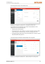
Page 88: ...To do so change the IP address of your computer laptop to 192 168 55 5 In Windows 10 press the key combination Windows R to open the Run dialog box Enter cmd Start the command prompt by entering ping 192 168 55 90 and pressing the Enter key If the energy meter is reachable Windows will send four data packages to the IP address and will receive responses 6 3 Settings in the web visualisation Loggin...

Page 89: ...be connected to ports XF14 or XF15 on the front of the ControlShield for commissioning Enter the address 192 168 55 10 webvisu in the web browser The INTILION web visualisation will open see illustration below At the top right of the interface there is the option to set the language to either German DE or English EN Illustration 51 INTILION web visualisation ...

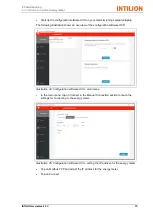
Page 90: ...or the installation technician Illustration 52 INTILION user interface The following interface can be opened by clicking on the Configuration icon second from the left All of the necessary configurations for the commissioning of the battery storage system can be set on this page Illustration 53 INTILION configuration interface On the left hand section of the page is a table with a black background...

Page 91: ...lo Gavazzi EM24 energy meter The value 6 is entered if there is no installed energy meter and the battery storage system is being operated with the Setpoint specification application The value 5 is entered if two Carlo Gavazzi EM24 energy meters can be incorporated The second energy meter can be used to receive additional energy flows such as the energy generated by a PV system The system is curre...

Page 92: ...ystem In order to ensure maximum self sufficiency the entire amount of energy supplied within the customer network is covered by private consumption The threshold is therefore usually set to 0 kW Illustration 55 INTILION interface for optimisation of energy consumption Peak shaving application With this application you will need to enter the threshold maintained by the battery storage system The 1...

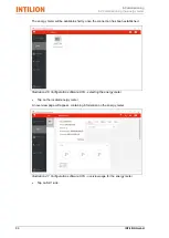
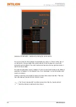
Page 93: ... be clarified with INTILION An individual assessment is always necessary here Illustration 57 INTILION interface for E mobility Clicking on the Play icon adopts and saves all of the settings These are then automatically imported into the Actual column Entering serial numbers The serial numbers for the lithium ion batteries for all scaleblocs need to be entered in the table with black background on...

Page 94: ...bloc The serial numbers are located at the top right hand side on the front of the modules The left and right arrows next to scalebloc 0 can be used to switch between the different scaleblocs scalebloc 0 is the Master here For n scaleblocs n x 9 serial numbers will need to be entered Clicking on the Play icon adopts and saves all of the entered serial numbers These are then automatically imported ...

Page 95: ...INTILION scalebloc 0 5C 93 6 4 Filling in the commissioning log Carry out additional tasks as per the commissioning log and make a note of the results 6 5 6 6 ...

Page 96: ...nel A onto the ControlShield is described below The panels B are installed in a similar way for the converter the BMS and the installation areas Illustration 59 Securing the panels for the ControlShield and the installation areas Remove any parts lying around in the battery storage system e g tools or cable debris Secure each panel with four screws 1 Tighten the screws on the panels to a tightenin...

Page 97: ... provide you with any technical information you may require HOPPECKE Service Competence Center Tel 49 0 800 246 77 32 German Tel 49 0 180 522 99 99 international Fax 49 0 2963 61 543 E mail service hoppecke com Our employees are also always interested in any information or feedback on your experiences with actual use that may be useful for us in improving our products ...

Page 98: ...6 Commissioning 6 8 Contacting the Hoppecke Service team 96 INTILION GmbH ...

Page 99: ...e Man for seven seconds before then being set back to automatic mode Auto Safety measures in normal operation The battery storage system must only be opened by persons who are qualified and or trained in this operation see Section 2 2 Personnel requirements There must be no unauthorised persons in or around the battery storage system No safety or protective devices may be removed or rendered non f...

Page 100: ......

Page 101: ...INTILION scalebloc 0 5C 99 8 Fault In the event of malfunctions please contact INTILION GmbH via the HOPPECKE Service Competence Center see Section 1 5 Service customer service ...

Page 102: ...8 Fault 100 INTILION GmbH ...

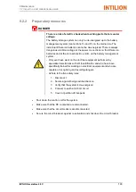
Page 103: ...lists Wear the personal protective equipment necessary for the work in question Block off access to the working area of the battery storage system Make sure that there are no unauthorised persons in the working area of the battery storage system Make sure that all assemblies components have cooled down to ambient temperature Carry out work on low components from a squat position not by bending ove...

Page 104: ...ng area Make sure that all of the safety devices in the battery storage system are working perfectly again Once all maintenance work is complete close all doors on the battery storage system 9 2 Inspection and maintenance work 9 2 1 Maintenance intervals Maintenance point Annually Entire battery storage system Carry out a visual inspection check screw connections 9 2 3 1 Lithium ion batteries Visu...

Page 105: ... B on the battery management system Only ever have work on the electrical equipment performed by specialised electricians with WLE certification and who have been specifically trained for working on electrical equipment and who are capable of recognising and avoiding dangers Adhere to the five safety rules 1 Disconnect 2 Secure against being switched back on 3 Verify that the system is de energise...

Page 106: ...ve the protective cap Report any damage to the operating company immediately Check that the flow off of condensate in the AC unit is guaranteed Check the screw connections Check that all of the screw connections on the battery storage system are secure Tighten any loose screw connections screw torques according to screw size and strength class 9 2 3 2 Lithium ion batteries Carry out a visual inspe...

Page 107: ...Check the sealing elements on the doors for wear Replace any worn sealing elements 9 2 4 Special maintenance intervals 9 2 4 1 AC unit Clean the AC unit air filter at least every 3 months Information on maintenance work to be performed on the AC unit can be found in the documentation from INTILION GmbH 9 2 4 2 Electrical equipment DANGER Risk to life due to electric shock Live components can cause...

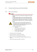
Page 108: ...system manager must be on site at the system and must ensure that no switching operations are performed on site within the operating company s electrical infrastructure up to the connection point of the network operator They can be reached by telephone Quick access to the battery storage system is guaranteed The battery storage system is in the state defined by INTILION GmbH The battery storage sy...

Page 109: ...ttery management system Only ever have work on the electrical equipment performed by specialised electricians with WLE certification and who have been specifically trained for working on electrical equipment and who are capable of recognising and avoiding dangers Adhere to the five safety rules 1 Disconnect 2 Secure against being switched back on 3 Verify that the system is de energised 4 Connect ...

Page 110: ...e to incorrect removal of the lithium ion batteries Incorrect removal of the lithium ion batteries leads to ergonomic hazards Proceed as follows when carrying and putting down the lithium ion batteries Position your body as close to the load as possible and make sure to stand in front of the load where possible Position your feet at least hip width apart Make sure that your feet are fully and secu...

Page 111: ...securely in position 10 2 2 Disassembly work 10 2 2 1 Discharging the lithium ion batteries Open the doors of the battery storage system The doors can be locked open at two positions 90 and 120 opening angles Make sure to undo the latching hooks first when subsequently closing the doors Discharge the lithium ion batteries To do so please contact the HOPPECKE Service Competence Center see Section 1...

Page 112: ... panels for the ControlShield and the installation areas Remove the four screws 1 and remove the panel 10 2 2 3 Disassembling the communication control and power cables Illustration 62 Removing the floor plates Remove floor plates 1 to 5 Disassemble the Icotek frame from the floor plate 3 Undo the screws on the Icotek frame and remove the cables Remove the Icotek grommets from the cables Disassemb...

Page 113: ...ve the four screws 1 and 2 and remove the panels for the battery management system BMS and the inverter 10 2 2 5 Disassembling the panels for the fire protection modules The procedure for the disassembly of a panel is described below Disassembly is performed in a similar way for the other panels Illustration 64 Disassembling the panel for the fire protection modules Remove the screws 1 and remove ...

Page 114: ...ctions on the lithium ion batteries Proceed step by step when disassembling When removing the safety caps from a lithium ion battery make sure that the safety caps are in place on the respective poles on all other lithium ion batteries Illustration 65 Lithium ion batteries removing the safety caps Push the safety caps on the poles 1 upwards 2 and remove in the direction of the arrow 3 Disassemble ...

Page 115: ...isk of injury due to incorrect lifting of the lithium ion batteries The lithium ion batteries are heavy Incorrect lifting of the lithium ion batteries leads to ergonomic hazards Lift the lithium ion batteries without straining your back see also the note at the start of this section Only ever lift the lithium ion batteries with the assistance of a second person Illustration 66 Lithium ion batterie...

Page 116: ...observed After removal store the lithium ion batteries in suitable packagings please read Section 10 3 Disposal for information regarding the disposal of lithium ion batteries 10 2 2 8 Removing the earthing points Illustration 67 Disassembling the earthing system for rack rails Undo the earthing system for the rack rails at position 1 Illustration 68 Disassembling the foundation earthing system Un...

Page 117: ...floor plates Insert the side panels and push them backwards to the back of the battery storage system Secure the side panels using the previously removed screws Illustration 69 Securing the front panel Insert the front panel and push it as far as it will go approx 10 mm in the direction of the arrow Secure the front panel using the previously removed screws 1 Close the doors of the battery storage...

Page 118: ...rson to secure the transport route Keep the working area neat and tidy Make sure that there are no persons in the path of travel or underneath suspended loads Do not use pipelines or attachment parts as attachment points Transport lugs on components e g electric motor are only intended for lifting the individual components and not for lifting the entire battery storage system Only lift the battery...

Page 119: ...chment points are located on the top of the battery storage system underneath the covers Illustration 70 Overview of the attachment points 1 Attachment points 4 points Illustration 71 Removing the covers over the attachment points Remove the covers over the attachment points 1 and attach the shackle or hook ...

Page 120: ...Keep the working area neat and tidy Make sure that there are no persons in the path of travel or underneath suspended loads Always lift the battery storage system slowly and carefully in order to ensure safety and stability Guide the battery container through a rope in order to prevent swinging or twisting Load the battery storage system Remove the shackles or hooks and secure the covers over the ...

Page 121: ...sal INTILION scalebloc 0 5C 119 11 Applicable documents The following documents are attached to this operating manual in the form of appendices EU Declaration of Conformity Overview wiring diagram Technical data sheet Commissioning log ...

Reviews: