background image


2 Safety 

2.6 Special warnings 


22


INTILION GmbH 

2.6.2 

Danger due to electrical energy 


DANGER 


There is a risk of electric shock when touching parts that are under 
voltage. This also poses a  danger of secondary accidents as a result 
of shock (e.g. falls). 

– 

Keep electrical components closed at all times. 

– 

Only ever have work on the electrical equipment performed by 
specialised electricians with WLE certification and who have been 
specifically trained for working on electrical equipment and who are 

capable of recognising and avoiding dangers. 

– 

Adhere to the five safety rules when working on the electrical equipment: 

1.  Disconnect 

2.  Secure against being switched back on 

3.  Verify that the system is de-energised 

4.  Connect to earth and short circuit 

5.  Cover or partition off live parts 


In order to ensure the safe performance of electrical work, the operating company 
can transfer its obligations over to a system manager (specialised electrician). 

The transfer of responsibility must be made in writing. 


– 

Before working on the electrical equipment, de-energise the battery storage system 
and secure it against re-activation. 


DANGER 


There is a risk of electric shock when touching parts that are under 
voltage. 

Because the system contains batteries that cannot be de-energised, 
life-threatening DC voltages are always present in some sub-areas of 
the system.


The battery storage system can only be de-energised up to the battery 
management system (connections P+ and P-) on the mains side. The 
individual battery modules cannot be de-energised. There is always 
dangerous electrical voltage at the power connections on the battery 
modules and at the connections B+ and B- on the battery management 
system. 


Summary of Contents for scalebloc energy

Page 1: ... original operating manual INTILION GmbH Dr Sinsteden Straße 8 D 08056 Zwickau Telephone 49 0 375 270 550 0 Fax 49 0 375 270 550 300 E mail contact intilion com Internet www intilion com Store for future use INTILION scalebloc energy INTILION scalebloc power INTILION scalebloc power boost ...

Page 2: ...his operating manual and all of the illustrations contained within are copyright protected Any use that goes beyond the limits of copyright law without the prior written consent of the publisher is impermissible and punishable by law This applies in particular to reproduction translations microfilming storage and processing using electronic systems ...

Page 3: ... 2 2 4 Training 18 2 3 Personal protective equipment 18 2 4 General safety information 19 2 5 Safety measures for environmental protection 20 2 6 Special warnings 21 2 6 1 Symbols used on the battery storage system 21 2 6 2 Danger due to electrical energy 22 2 6 3 Danger due to lithium ion batteries 24 2 6 4 Dangers due to hot surfaces 25 2 6 5 Dangers due to working at height 25 2 6 6 Dangers due...

Page 4: ...storage system and securing in place 50 5 6 Earthing the battery storage system 52 5 7 Installing the alarm 53 5 8 Inserting the battery modules 55 5 9 Battery module power cabling 59 5 10 Connecting the communication control and power cables 64 5 11 Final measures 66 5 12 Establishing the mains connection 68 5 13 Connecting the energy meter 69 5 14 Setpoint specification communication connection ...

Page 5: ...ssembly 106 10 2 1 Information regarding hazards during disassembly 106 10 2 2 Disassembly work 107 10 2 2 1 Discharging the battery modules 107 10 2 2 2 Disassembling the panels 107 10 2 2 3 Disassembling the communication control and power cables 108 10 2 2 4 Disassembling the panels for the battery management system BMS and the inverter 109 10 2 2 5 Disassembling the panels for the fire protect...

Page 6: ...he door of the AC unit 54 Illustration 23 Installed alarm 54 Illustration 24 Battery module on delivery 56 Illustration 25 Battery module opening the box 56 Illustration 26 Battery module removing from box 57 Illustration 27 Battery modules securing in the fire protection housing 58 Illustration 28 Battery module removing the safety caps 60 Illustration 29 Wiring diagram 61 Illustration 30 Laying ...

Page 7: ...INTILION web visualisation interface for E mobility 91 Illustration 64 INTILION web visualisation interface for entering the serial numbers 92 Illustration 65 INTILION web visualisation performance run 93 Illustration 66 Panel for the fire protection housing 94 Illustration 67 Panel for the BMS inverter the ControlShield and the installation areas 94 Illustration 68 Inserting the Icotek grommets i...

Page 8: ...ng 18 Tab 2 Technical specifications INTILION scalebloc battery storage system 40 Tab 3 Technical specifications battery modules 41 Tab 4 Transformer based on power output 70 Tab 5 Connecting the control cables 74 Tab 6 Maintenance intervals 100 ...

Page 9: ...intenance decommissioning and disassembly of the battery storage system This applies in particular to the specified safety instructions After reading the operating manual you will be able to Commission the battery storage system Operate the battery storage system in compliance with the safety standards Properly maintain the battery storage system Decommission and disassemble the battery storage sy...

Page 10: ...section Structure SIGNAL WORD Symbol providing more details on a hazard Hazard type and source Possible consequence s of non observation Measure s for risk prevention Hazard levels DANGER Hazard with a high level of risk that if not avoided can lead to death or serious bodily injury WARNING Hazard with a medium level of risk that if not avoided can lead to death or serious bodily injury CAUTION Ha...

Page 11: ...g activities that need to be performed in the order in which they are listed Text in quotation marks constitutes references to other chapters or sections 1 1 4 Symbols used in this manual Particular hazards are indicated as follows in the form of warnings Warning of electrical voltage This symbol warns of the risk to life due to dangerous electrical voltage Warning of the danger danger due to lith...

Page 12: ...ery storage system with faulty safety devices or with improperly fitted or non functioning safety and protective equipment Failure to observe the operating manual and the instructions in the operating manual with regard to the installation commissioning operation and maintenance of the battery storage system Use of non qualified or untrained personnel Structural modifications to the battery storag...

Page 13: ...scharged until the discharge end voltage or a State of Charge SoC of 0 is reached whichever comes first with a current rate of 1 5 C 1 C corresponds to current in amperes A which in this case has the same value as the nominal capacity of a cell in ampere hours Ah The battery storage system is left in active standby for 30 minutes The battery storage system must be fully charged using the CCCV Cons...

Page 14: ... written approval of INTILION GmbH Infringements will lead to liability for damages The right to make any further claims remains reserved 1 5 Service customer service INTILION GmbH is part of the HOPPECKE Group Our customer service team is available to provide you with any technical information you may require HOPPECKE Service Competence Center Tel 49 0 2963 61 591 Fax 49 0 2963 61 543 E mail serv...

Page 15: ...st also observe any existing national working operating and safety regulations Any existing internal site regulations must also be observed 2 1 Intended use The operational safety of the battery storage system is only guaranteed if it is used as intended The INTILION scalebloc is an AC coupled battery storage system and is only suitable for the following application Behind the meter application Th...

Page 16: ... acceptance are performed based on the German Product Safety Act ProdSG Produktsicherheitsgesetz No modifications additions or conversions may be made to the battery storage system without the prior written approval of INTILION GmbH The product will lose its EU conformity in the event of non compliance The manufacturer of the battery storage system is outside of the warranty and any warranty claim...

Page 17: ...he nominal values Do not operate the battery modules outside of the operating conditions defined in the data sheet Do not expose the lithium ion cells of the battery storage system to ambient temperatures of above 55 C or below 0 C e g when in storage When the battery storage system is connected to the power supply the integrated AC unit ensures that the temperature requirements are met Avoid shor...

Page 18: ...nel Trained personnel Trained personnel have been instructed by the operating company or by qualified personnel on the tasks assigned to them and the potential hazards involved with improper conduct as part of a training session Qualified personnel Qualified personnel are those who because of their training knowledge and experience coupled with knowledge of the applicable regulations are in a posi...

Page 19: ...y storage system under the supervision of qualified personnel Successfully completed training must be confirmed in writing The operating company is responsible for personnel training 2 2 2 Obligations of personnel All persons assigned with work on the battery storage system are obligated to do the following prior to starting work Observe the basic requirements regarding occupational safety and acc...

Page 20: ...ains or other jewellery The symbols have the following meanings Wear protective clothing isolating protective clothing Protective work clothing is closely fitting work clothing with a low tear resistance with narrow sleeves and no protruding parts It is primarily intended for protection against being caught by moving product parts Isolating protective clothing is non conductive and prevents the pa...

Page 21: ...damage Wear a harness Use suitable fall protection safety cable and harness when working at heights Personal protective equipment must be provided by the operating company and must comply with the applicable requirements The national regulations and specifications from the workplace risk assessment must also be observed along with any internal instructions from the operating company 2 4 General sa...

Page 22: ...te The qualified person on site may act immediately in the event of an error e g by carrying out a reboot or importing the old runnable version Take the battery storage system out of operation immediately in the event of malfunctions Have the malfunctions rectified by appropriately trained specialists or by INTILION GmbH or the HOPPECKE Service team Always store the operating manual in the locatio...

Page 23: ...nauthorised persons Hazards cannot be recognised by unauthorised persons No access for persons with pacemakers or defibrillator implants This symbol prohibits the presence of persons with medical implants in the area of the battery storage system as the electromagnetic fields risk causing devices such as pacemakers to malfunction No open flames fire open ignition sources and smoking are prohibited...

Page 24: ...it 5 Cover or partition off live parts In order to ensure the safe performance of electrical work the operating company can transfer its obligations over to a system manager specialised electrician The transfer of responsibility must be made in writing Before working on the electrical equipment de energise the battery storage system and secure it against re activation DANGER There is a risk of ele...

Page 25: ...carrying device and with a weight that means that it cannot be easily moved This also includes electrical operating equipment that is permanently attached on a temporary basis and that is operated via moving connection cables At least every 6 months have a specialised electrician check the portable electrical operating equipment the connection cables with connectors and the extension and device co...

Page 26: ...king on the battery modules Only transport the battery modules in their original packaging or in packaging that corresponds to the applicable guidelines Keep the packagings in a safe place Do not heat up the battery modules beyond the maximum permissible temperature and do not burn them Make sure that there are no external ignition sources Do not short circuit the battery modules and do not cause ...

Page 27: ...red eye if applicable In the event of swallowing consult a doctor immediately No not induce vomiting Rinse the mouth and surrounding areas with water 2 6 4 Dangers due to hot surfaces WARNING Contact with hot components may cause burns Always wear protective work clothing and protective gloves when working near hot components Allow components to cool down to ambient temperature before working on t...

Page 28: ...levels of 80 dB A and over Ear protection must be work at sound pressure levels of 85 dB A and over 2 6 7 Dangers due to the use of incorrect spare parts NOTE Incorrect or faulty spare parts can lead to damage malfunctions or total failure and can also impair safety Only use original spare parts Procure spare parts from INTILION GmbH The necessary information regarding spare parts can be found in ...

Page 29: ...been secured against re activation Check all of the safety devices on the battery storage system for correct functioning on a regular basis 2 8 Information regarding emergencies Preventative measures Always be prepared for accidents or fire Keep first aid equipment first aid kit blankets etc to hand Make sure that you are familiar with the accident reporting first aid fire extinguishing and rescue...

Page 30: ...erating company must only allow people to work on the battery storage system who have the appropriate qualifications and training The operating company must ensure that all employees who work with the battery storage system have read and understood the operating manual It must also provide employees with regular documented training and must inform them of the associated dangers The operating compa...

Page 31: ...stem manager is responsible for the safe performance of electrical work The transfer of responsibility is performed in writing by the operating company The system manager must have read and understand the operating manual He or she must consult the HOPPECKE Service Competence Center in the event of misunderstandings ...

Page 32: ...ed energy management system EMS external customer interfaces and the safeguarding and control of internally connected components such as climate control Applications include behind the meter use which improves the private consumption of locally generated energy to reduce load peaks in industrial environments and for pre load storage with regard to electromobility infrastructure The energy flow con...

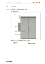
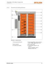
Page 33: ...torage system 3 2 Overview INTILION scalebloc 31 3 2 Overview 3 2 1 Overview of functional elements View with closed door Illustration 1 Functional elements view with closed door 1 LTE antenna 3 Door 2 AC unit 4 Outdoor housing IP55 ...

Page 34: ...ew 32 INTILION GmbH View with open door Illustration 2 Functional elements view with open door 1 Fire protection housing with battery module 5 Battery management system BMS 2 Socket 6 Inverter 3 Installation area 7 ControlShield 4 Temperature sensor PT1000 ...

Page 35: ...ety devices Illustration 3 Safety devices 1 Visual and acoustic alarm 4 Smoke degasification duct see Section 3 2 4 7 Smoke degasification duct 2 Smoke detector 5 Door contact switch 3 Fire protection housing 6 ControlShield EMERGENCY STOP CONTACTS option of integration into the emergency stop circuit ...

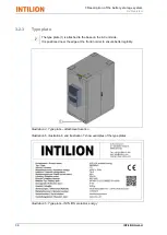
Page 36: ... 1 is attached to the base on the AC unit side It is positioned near the edge at the front in order to ensure better legibility Illustration 4 Type plate attachment location Illustration 5 Illustration 6 and Illustration 7 show examples of the type plates Illustration 5 Type plate INTILION scalebloc energy ...

Page 37: ...3 Description of the battery storage system 3 2 Overview INTILION scalebloc 35 Illustration 6 Type plate INTILION scalebloc power Illustration 7 Type plate INTILION scalebloc power boost ...

Page 38: ...ntinually illuminate 3 2 4 2 Door contact switch Illustration 9 Door contact switch The door contact switch monitors the doors of the battery storage system The AC unit will switch off if the doors are opened If the doors stay open for more than 30 minutes the system will shut down This status is signalled by the alarm the signal horn will repeatedly sound briefly and the signal light will repeate...

Page 39: ...e form of a repeated brief tone The alarm is attached to the battery storage system on delivery It is positioned rotated by 90 and is then assembled on site see Section 5 7 Installing the alarm 3 2 4 4 Emergency stop contacts There are connection terminals on the ControlShield for the integration of an emergency stop switch or an emergency stop safety circuit If this circuit is interrupted the bat...

Page 40: ... the wiring can be found in the General connection diagram which is available from INTILION GmbH upon request The grid and plant protection is to be provided as central grid and plant protection in the customer system 3 2 4 6 Fire protection housing The fire protection housing is a mechanical housing for battery modules with prismatic cells Prismatic lithium ion cells have a venting valve which op...

Page 41: ...act your installation specialist if you have any questions The smoke degasification duct is located in the base of the battery storage system and is connected to the inside of the control cabinet The gas is guided to the outside via the smoke degasification duct thereby preventing the potential consequences of the gas for the system and the direct vicinity The operating company is responsible for ...

Page 42: ... oxide Configuration 9 battery modules of 22 cells each Cell arrangement 198S1P Energy content usable 61 6 kWh Voltage nominal 729 V Mains connection 400 V 3 phase Power max 25 kVA 50 kVA 68 5 kVA Dimensions W x H x D approx 1618 mm x 2000 mm x 1026 mm 1674 mm x 2125 mm x 1026 mm 1674 mm x 2125 mm x 1026 mm Weight approx 930 kg 962 kg 995 kg Housing Outdoor housing IP55 Airborne sound emissions A ...

Page 43: ... Ah Voltage nominal 728 6 V Voltage range 633 6 V 821 7 V Power max constant 68 5 kW 1 C Efficiency 98 Weight 486 kg 9 modules at 54 kg each Battery module Samsung SDI Cell arrangement 22S1P Energy content nominal 7 61 kWh Capacity nominal 94 Ah Voltage nominal 81 V Voltage range 70 4 V 91 3 V Power max constant 7 61 kW 1 C Weight 54 kg Dimensions W x H x D 370 mm x 160 mm x 650 mm Battery cell Sa...

Page 44: ...tion of the battery storage system please contact INTILION GmbH and observe the following information Battery modules Only transport and store the battery modules in their original packaging or in packaging that corresponds to the applicable guidelines Symbols on the packaging must be observed The battery modules must not be removed from their packaging until shortly before insertion into the rack...

Page 45: ...rsonnel without fail For information on changing the location of the battery storage system please contact INTILION GmbH Unless specified otherwise the transport conditions from Section 4 Transport and storage apply 5 1 Information regarding hazards during installation Installation must only be performed by appropriately trained and qualified personnel and in compliance with all of the safety inst...

Page 46: ...eep a safe distance to transport routes Use collision protection e g bollards protective edges or similar to protect the battery storage system if installation is being performed in an urban area or in a location where there are other moving vehicles Ensure a minimum distances of 1300 mm here We recommend securing the battery storage against unauthorised access touching e g by means of a fence WAR...

Page 47: ...tration 12 example illustration Illustration 12 Maintenance areas Requirements for the floor area WARNING Loss of stability A loss of stability can lead to a significant risk of injury The floor area must be even The foundation must have a load bearing capacity of at least 1 t m The operating company is responsible for the static properties of the foundation Please contact INTILION GmbH or a distr...

Page 48: ...able 5 4 Disassembling the transport pallet The battery storage system is delivered on a transport pallet The fixing screws must be removed prior to unloading Illustration 13 Disassembling the transport pallet removing the fixing screws Remove the fixing screw 1 at each corner Illustration 14 Disassembling the transport pallet removing the floor plates If present remove the floor plates 1 to 5 The...

Page 49: ...ical drawings of the base for scalebloc versions energy power and power boost This drawing can be used to ascertain the drill measurements for the attachment of the anchors slots A base template can be requested from INTILION GmbH to help with assembly Illustration 15 Base for base height of 100 mm INTILION scalebloc energy only Illustration 16 Base for base height of 200 mm INTILION scalebloc all...

Page 50: ... transport route Keep the working area neat tidy and free of trip hazards Make sure that there are no persons in the path of travel or underneath suspended loads Do not use pipelines or attachment parts as attachment points Only lift the battery storage system at the designated points Always lift the battery storage system slowly and carefully in order to ensure safety and stability Guide the batt...

Page 51: ...e attachment points are located on the top of the battery storage system underneath the covers Illustration 17 Overview of the attachment points 1 Attachment points 4 points Illustration 18 Removing the covers over the attachment points If present remove the covers over the attachment points 1 and attach the shackle or hook ...

Page 52: ...safety vest and a safety helmet Always have an addition person to secure the transport route Keep the working area neat and tidy Make sure that there are no persons in the path of travel or underneath suspended loads Always lift the battery storage system slowly and carefully in order to ensure safety and stability Guide the battery storage system through a rope in order to prevent swinging or twi...

Page 53: ...ers over the attachment points Tighten the screws to a tightening torque of max 5 Nm Screw the battery storage system onto the foundation The tightening torque is dependent upon the size of the screws anchors being used With an M10 thread the tightening torque must be at least 45 Nm Follow these steps in reverse order to secure the floor plates It helps to initially leave the floor plate with Icot...

Page 54: ...cted in the base by an earthing conductor to the main earthing rail The minimum cross section of the earthing conductor is 16 mm Illustration 20 Securing the foundation earthing system From the outside secure the foundation earthing system designated earthing point to the inside of the battery storage system at position 1 Alternatively a check can be carried out to determine whether the system can...

Page 55: ...g protection earthing in addition to the foundation earthing system earthing electrode type B earthing rods can also be used earthing electrode type A 5 7 Installing the alarm The visual and acoustic alarm is attached above the AC unit to the housing of the battery storage system For electrical connection the W4 cable of the cable harness on the AC side is to be used The alarm is initially open fo...

Page 56: ... AC unit Wiring takes place based on the wiring diagram provided wire 1 is to be placed on X1 wire 2 on X2 and wire 3 on X3 and secured The alarm is then to be installed on the mounting bracket above the AC unit by fixing it with two screws M4 x 20 at the provided position Illustration 23 Installed alarm ...

Page 57: ...boots and a safety helmet Observe the documentation from the supplier CAUTION Risk of injury due to incorrect lifting and insertion of the battery modules Incorrect lifting and insertion of the battery modules leads to ergonomic hazards Proceed as follows when lifting and carrying the battery modules Position your body as close to the load as possible and make sure to stand in front of the load wh...

Page 58: ... transport Check the packaging and the battery modules for damage Only use undamaged battery modules Contact the HOPPECKE Service team if the packaging or the battery modules are damaged Illustration 24 Battery module on delivery The battery modules are delivered in individual boxes Each battery module is protected by shock absorbing cardboard and a film Illustration 25 Battery module opening the ...

Page 59: ...lso the note at the start of this section Only ever lift the battery modules with the assistance of a second person Wear protective gloves when lifting the lithium ion batteries Illustration 26 Battery module removing from box Lift the battery module out of the box at the gripping points 1 Make sure that the protective caps are fitted on the poles of the lithium ion batteries Also make sure not to...

Page 60: ...der any circumstances Illustration 27 Battery modules securing in the fire protection housing Secure each battery module to the fire protection housing using four screws 1 Use an isolated torque wrench to tighten the screws to a tightening torque of 5 1 to 6 1 Nm Note the serial number of the battery modules The serial numbers consist of 16 digits and are located on the front of the battery module...

Page 61: ... For safety reasons among others installation is prohibited without valid training by INTILION GmbH Wear arc proof work clothing 1000V protective gloves safety boots and a safety helmet with visor to protect against arcs The visor must be kept closed at all times when carrying out subsequent work Use only insulated tools Place at least one 1 5 m x 1 5 m rubber mat in front of the battery storage s...

Page 62: ...k Follow the sequence described below when wiring up the battery modules and when connecting them to the battery management system BMS NOTE Before every installation step make sure to only remove the safety caps for the battery modules specified in the relevant instruction step This includes the specified poles Otherwise the exposed poles of the battery modules that are not specified in the instal...

Page 63: ...he battery storage system bottom end or are guided out at the top of the central web and are located between the battery module fire protection housings and the roof of the battery storage system top end Illustration 29 Wiring diagram Connect the cable with the marking shown in yellow in the diagram bottom end to connection B on the battery management system BMS Put the safety caps back on Connect...

Page 64: ... long cell connector to connect the positive pole of battery module 3 to the negative pole of battery module 4 Put the safety caps back on Use the 630 mm long cell connector to connect the positive pole of battery module 4 to the negative pole of battery module 5 Put the safety caps back on Use the 630 mm long cell connector to connect the positive pole of battery module 5 to the negative pole of ...

Page 65: ...connection FAN PWR OUT to battery module 1 connection FAN WR left Use the 300 mm long control cable to connect battery module 1 connections COMM OUT and FAN PWR right to battery module 2 connections COMM IN and FAN PWR left Use the 300 mm long control cable to connect the remaining battery modules to one another in accordance with the previous instruction No control cable is connected to the outpu...

Page 66: ...screwing them into the Icotek frame in their almost final position not yet connected see Illustration 31 Illustration 31 Icotek frame 1 Icotek frame 2 Grommets In order to guarantee that the battery storage system has IP 55 protection the cables need to have the Icotek frame and the correct Icotek grommet Disassemble the Icotek frame from the floor plate Place the suitable Icotek grommets around t...

Page 67: ...ap that closes when pressure is applied Illustration 32 Icotek grommet suitable for cable Unsuitable Icotek grommet Illustration 33 The Icotek grommet is too small and does not fit around the cable Illustration 33 Icotek grommet not suitable for cable Thread the cable with Icotek grommet into the Icotek frame When doing so make sure that the flat sides of the Icotek grommets are resting against on...

Page 68: ...gh 5 11 Final measures Illustration 34 Securing the front panel Insert the side panels and push them backwards to the back of the battery storage system Insert the front panel and push it as far as it will go approx 10 mm in the direction of the arrow Secure the front panel using the previously removed enclosed screws 1 Carry out a visual inspection In particular check whether there are any tools ...

Page 69: ...o the AC unit door can be opened by a maximum of 90 Adjust the setpoints to 23 C for Controls Condenser Blower Compressor 1 and to 16 C for Controls Heater 2 The following illustrations Illustration 35 show the positions of the adjustment elements in the AC unit Illustration 35 Adjusting the AC unit 23 C 16 C ...

Page 70: ...ng all of the ControlShield circuit breakers to the open OFF position Illustration 36 centre The applicable VDE provisions and the technical connection conditions TAB of the local electricity supply company must be complied with when establishing the mains connection The battery storage system has a power output of 25 kVA 50 kVA or 68 5 kVA per outdoor control cabinet The power cable must be set u...

Page 71: ... for example conversion transformers With conversion transformers the measuring device can be retrofitted without interrupting the power supply The measuring device should be positioned directly at the mains connection point on the low voltage side e g near to the central meter that measures the total supply and possibly also the total feed from the customer s system Illustration 37 Energy meter c...

Page 72: ...AV53XE1X energy meter see Section 6 2 Commissioning the energy meter The transformer is selected based on the maximum power output that will be recorded by the measurements Ensure that the secondary current is scaled to 5 A Tab 4 shows the transformer to be used based on the mains power output Tab 4 Transformer based on power output Mains power output Transformer to be used Energy meter up to 100 ...

Page 73: ...f the energy meter When used in conjunction with the transformers the energy meter covers the functionality of the energy flow direction sensor required in relation to the VDE FNN note connection and operation of storage systems on low voltage networks It ensures that the battery storage system does not feed any energy into the public power grid Because the energy meter contains the energy flow di...

Page 74: ... and a defined data point list Defined parameters must be read out or specifically targeted A list of Modbus parameters is provided in a separate document The communication connection and readout of battery parameters are performed via the RJ45 port XF13 customer side interface of the ControlShield see Illustration 39 The required network cable must meet category 5 Cat 5 standards as a minimum and...

Page 75: ...from its LTE antenna fitted on the roof of the battery storage system above the AC unit and from the ControlShield type plate which is labelled with the word Master The communication cables and the optional control cables between the battery storage systems can be routed via the removable panels on the side and rear of the base see Illustration 40 Illustration 40 Feed throughs green for communicat...

Page 76: ... XD13 1 XD15 2 XD13 2 XD15 3 XD13 3 XD15 4 XD13 4 XD15 5 XD13 5 XD15 6 XD13 6 XD15 7 XD13 7 XD15 8 XD13 8 The information exchange between the master and the energy meter and the slaves using Ethernet ports XF14 and XF15 takes place via the communication cables shown in red in Illustration 41 These cables are provided with each slave for outdoor use if more than one storage system is installed Ill...

Page 77: ...re commissionings contact INTILION GmbH see Section 1 5 Service customer service WARNING Risk of injury due to lack of space When commissioning the battery storage system there is a risk of injury such as scratches puncture wounds or fractures as a result of an excessively close arrangement of the necessary work equipment and or components Cordon off the danger zone Keep unauthorised persons away ...

Page 78: ...ess of your commissioning computer laptop This description is based on the operating system Windows 10 The control panel which is accessed either via the gear symbol on the left hand side of the Start menu or by typing control panel after pressing the Windows button can be seen in Illustration 43 To change the settings you will need to go to the Network and Internet area which will take you to the...

Page 79: ...st be used IP address 192 168 2 23 Subnet mask 255 255 255 0 The following numbers are blocked as IP addresses 10 to 29 reserved for control units 30 to 49 reserved for inverters 50 to 69 reserved for the BMS 90 reserved for energy meters Illustration 43 Control panel overview screen in Windows 10 Illustration 44 Network and Internet section of the control panel ...

Page 80: ...6 Commissioning 6 1 Preparatory work and information 78 INTILION GmbH Illustration 45 Network adapter settings Illustration 46 Options for the network adapter ...

Page 81: ...6 Commissioning 6 1 Preparatory work and information INTILION scalebloc 79 Illustration 47 Settings for the IP address the standard gateway and the DNS server ...

Page 82: ... on the energy meter display Use the left right joystick settings to scroll through the menu until the network settings appear IP subnet gateway DNS Make a note of the IP address the subnet mask and the gateway The following settings are used as standard by Carlo Gavazzi although these may deviate depending on the firmware of the energy meter IP address 192 168 1 20 Subnet mask 255 255 255 0 Gatew...

Page 83: ...rview of the configuration software UCS Illustration 48 Configuration software UCS main menu In the main menu tap on Connect in the Manual Connection section to reach the settings for connecting to the energy meter Illustration 49 Configuration software UCS setting the IP address for the energy meter Tap on Modbus TCP and adjust the IP address for the energy meter Tap on Connect ...

Page 84: ...y once the connection has been established Illustration 50 Configuration software UCS selecting the energy meter Tap on the located energy meter An overview page will appear containing information on the energy meter Illustration 51 Configuration software UCS overview page for the energy meter Tap on SETTINGS ...

Page 85: ...ion of the Electrical System tab Check the ratio on the transformer If the transformer has a ratio of 400 5 A for example then 400 A should be entered under Primary and 5 A under Secondary This gives a transformer ratio of 80 No changes should be made under VOLTAGE TRANSFORMER RATIO However check to make sure that the ratio is set to 1 0 Then open the page containing the network settings for the e...

Page 86: ...ata packages to the IP address and will receive responses 6 3 Filling in the commissioning log Execute the remaining commissioning steps in accordance with the commissioning log provided by INTILION GmbH and enter the results Information on the INTILION web visualisation and test mode can be found in Section 6 5 Settings in the web visualisation In accordance with DGUV Specification 3 BGV A3 the s...

Page 87: ... possible to configure further battery storage system settings in this mode see Section 6 5 Settings in the web visualisation a mains connection must be established for the test mode performance run required to complete the process 6 5 Settings in the web visualisation Logging in to the web visualisation The IP address of your computer laptop will need to be adjusted in order to access the web vis...

Page 88: ...aptop for commissioning must be connected to port XF13 customer side interface on the front of the ControlShield Enter the address https 192 168 2 2 webvisu in the web browser In the login window see Illustration 56 the following details are to be entered User name admin Password Intilion Illustration 56 Login window of the web visualisation ...

Page 89: ...visualisation Enter the following login details after clicking on the login icon User name Hoppecke Password Service The user interface for the commissioning technician appears Illustration 58 Illustration 58 INTILION web visualisation user interface The interface below can be opened by clicking on the Configuration icon second from the left Illustration 59 All of the necessary configurations for ...

Page 90: ...e The table with a black background in the top left hand corner of the screen is used to enter the number of scaleblocs the energy meter and the active applications The relevant information can be found in the adjacent table with a grey background Illustration 60 Illustration 60 INTILION web visualisation configuration interface excerpt ...

Page 91: ...ter Following consultation with INTILION GmbH other energy meters e g Janitza UMG 604E PRO can be integrated for specific applications 3 Number of active applications The number of applications to be adjusted should be entered here Information on the applications can be found in the remainder of this section The settings are adopted and imported into the Actual column by pressing the play icon at ...

Page 92: ...to enter the threshold maintained by the battery storage system Illustration 62 The 15 minute average power values are compensated above the set value If 1 is entered in the column for Pulse per kWh of S0 the S0 signal is transmitted from the central connection meter to DI1 XD14 5 in order to synchronise the timings of the 15 minute average power values Illustration 62 INTILION web visualisation i...

Page 93: ...ace for E mobility Clicking on the Play icon adopts and saves all of the settings These are then automatically imported into the Actual column Entering serial numbers The serial numbers for the battery modules for all scaleblocs must be entered in the table with the black background on the bottom right hand side of the web visualisation Alternatively for manual entry there is the option of reading...

Page 94: ...d right arrows next to scalebloc 0 can be used to switch between the different scaleblocs scalebloc 0 is the Master here For n scaleblocs n x 9 serial numbers will need to be entered Clicking on the Play icon adopts and saves all of the entered serial numbers These are then automatically imported into the Actual column The Cloud component ID and other values other than the serial numbers described...

Page 95: ...eted in line with the commissioning log Before the performance run fit all of the panels see Section 6 6 Fitting the panels except the panel for the ControlShield The ControlShield panel must only be fitted after the performance run Please note that the battery storage system must be connected to the mains to execute the performance run The performance run is started using the play icon The batter...

Page 96: ... BMS inverter the ControlShield and the installation areas For the fire protection housings the panels with louvered metal sheet and Icotek grommets are used For the power cable the Icotek grommets KT13 are used for the communication ventilator cables the Icotek grommets KT8 are used The procedure for the installation of a panel is described below Installation is performed in a similar way for the...

Page 97: ...tection housing Insert the Icotek grommets 1 into the recesses on the panel Make sure that the Icotek grommets are correctly positioned The flat side of the Icotek grommets must be pressing against the fire protection housing Illustration 69 Fastening the panel to the fire protection housing Attach the panel to the fire protection housing using six screws 1 Tighten the screws to a tightening torqu...

Page 98: ... lying around in the battery storage system e g tools or cable debris Secure each panel with four screws 1 Tighten the screws on the panels to a tightening torque of 5 Nm 6 7 Contacting the Hoppecke Service team Once the commissioning working steps have been completed contact the HOPPECKE Service Competence Center You will need to send them the completed commissioning log so that customer access c...

Page 99: ... mode Auto Status messages via optical signal states of the LED The current operating state of the battery storage system can be detected by various optical signals of the green LED on ControlShield Operating state of the battery storage system Status of the green LED on ControlShield Run Standby Permanently On Stop Starting 2 s On and 0 5 s Off EOL IBN SoH calibration manual mode Flashing at 0 5 ...

Page 100: ... 6 7 Contacting the Hoppecke Service team 98 INTILION GmbH 8 Fault In the event of malfunctions please contact INTILION GmbH via the HOPPECKE Service Competence Center see Section 1 5 Service customer service ...

Page 101: ...formed by qualified specialists Wear the personal protective equipment necessary for the work in question Block off access to the working area of the battery storage system Make sure that there are no unauthorised persons in the working area of the battery storage system Make sure that all assemblies components have cooled down to ambient temperature Carry out work on low components from a squat p...

Page 102: ...ices in the battery storage system are working perfectly again Once all maintenance work is complete close all doors on the battery storage system 9 2 Inspection and maintenance work 9 2 1 Maintenance intervals Tab 6 Maintenance intervals Component Maintenance work Section reference Annually Battery storage system Carry out a visual inspection check screw connections 9 2 3 1 Battery modules Visual...

Page 103: ...he connections B and B on the battery management system Only ever have work on the electrical equipment performed by specialised electricians with WLE certification and who have been specifically trained for working on electrical equipment and who are capable of recognising and avoiding dangers Adhere to the five safety rules 1 Disconnect 2 Secure against being switched back on 3 Verify that the s...

Page 104: ...ny damage to the operating company immediately Check that the flow off of condensate in the AC unit is guaranteed Check the screw connections Check that all of the screw connections on the battery storage system are secure Tighten any loose screw connections screw torques according to screw size and strength class 9 2 3 2 Battery modules Carry out a visual inspection and check the battery modules ...

Page 105: ...e performed on the AC unit can be found on the INTILION GmbH website 9 2 4 2 Inverter Replace the cooling fan after six years of operating time Information on maintenance work to be performed on the inverter can be found on the INTILION GmbH website 9 2 4 3 Electrical equipment DANGER Risk to life due to electric shock Live components can cause fatal electric shock if touched Work on the electrica...

Page 106: ...hin the operating company s electrical infrastructure up to the connection point of the network operator They can be reached by telephone Quick access to the battery storage system is guaranteed The battery storage system is in the state defined by INTILION GmbH The battery storage system can only be put back into operation following the update under the supervision of the system manager who coord...

Page 107: ...battery management system Only ever have work on the electrical equipment performed by specialised electricians with WLE certification and who have been specifically trained for working on electrical equipment and who are capable of recognising and avoiding dangers Adhere to the five safety rules 1 Disconnect 2 Secure against being switched back on 3 Verify that the system is de energised 4 Connec...

Page 108: ...jury due to incorrect removal of the battery modules Incorrect removal of the battery modules leads to ergonomic hazards Proceed as follows when carrying the battery modules and placing them down Position your body as close to the load as possible and make sure to stand in front of the load where possible Position your feet at least hip width apart Make sure that your feet are fully and securely i...

Page 109: ...ladder is securely in position 10 2 2 Disassembly work 10 2 2 1 Discharging the battery modules Open the doors of the battery storage system The doors can be locked open at two positions 90 and 120 opening angles Make sure to undo the latching hooks first when subsequently closing the doors Discharge the battery modules To do so please contact the HOPPECKE Service team see Section 1 5 Service cust...

Page 110: ... panels for the ControlShield and the installation areas Remove the four screws 1 and remove the panel 10 2 2 3 Disassembling the communication control and power cables Illustration 73 Removing the floor plates Remove floor plates 1 to 5 Disassemble the Icotek frame from the floor plate 3 Undo the screws on the Icotek frame and remove the cables Remove the Icotek grommets from the cables Disassemb...

Page 111: ...he four screws 1 and 2 and remove the panels for the battery management system BMS and the inverter 10 2 2 5 Disassembling the panels for the fire protection housings The procedure for the disassembly of a panel is described below Disassembly is performed in a similar way for the other panels Illustration 75 Disassembling the panels for the fire protection housings Remove the screws 1 and remove t...

Page 112: ...power connections on the battery modules Proceed step by step when disassembling When removing the safety caps from a battery module make sure that the safety caps are in place on the respective poles on all other battery modules Illustration 76 Battery module removing the safety caps Push the safety caps on the poles 1 upwards 2 and remove in the direction of the arrow 3 Disassemble the cables Pu...

Page 113: ...plier CAUTION Risk of injury due to incorrect lifting of the battery modules The battery modules are heavy Incorrect lifting of the battery modules leads to ergonomic hazards Lift the battery modules without straining your back see also the note at the start of this section Only ever lift the battery modules with the assistance of a second person Illustration 77 Battery module disassembly from the...

Page 114: ...st be observed After removal store the battery modules in suitable packaging please read Section 10 3 Disposal for information regarding the disposal of battery modules 10 2 2 8 Removing the earthing points Illustration 78 Disassembling the earthing system for rack rails Undo the earthing system for the rack rails at position 1 Illustration 79 Disassembling the foundation earthing system Undo the ...

Page 115: ...or plates Insert the side panels and push them backwards to the back of the battery storage system Secure the side panels using the previously removed screws Illustration 80 Securing the front panel Insert the front panel and push it as far as it will go approx 10 mm in the direction of the arrow Secure the front panel using the previously removed screws 1 Close the doors of the battery storage sy...

Page 116: ...n to secure the transport route Keep the working area neat and tidy Make sure that there are no persons in the path of travel or underneath suspended loads Do not use pipelines or attachment parts as attachment points Transport lugs on components e g electric motor are only intended for lifting the individual components and not for lifting the entire battery storage system Only lift the battery st...

Page 117: ...ent points are located on the top of the battery storage system underneath the covers Illustration 81 Overview of the attachment points 1 Attachment points 4 points Illustration 82 Removing the covers over the attachment points Remove the covers over the attachment points 1 and attach the shackle or hook ...

Page 118: ...t route Keep the working area neat and tidy Make sure that there are no persons in the path of travel or underneath suspended loads Always lift the battery storage system slowly and carefully in order to ensure safety and stability Guide the battery storage system through a rope in order to prevent swinging or twisting Load the battery storage system Remove the shackles or hooks and secure the cov...

Page 119: ...117 11 Applicable documents The following documents are attached to this operating manual in the form of appendices EU Declaration of Conformity Overview wiring diagram for the scalebloc versions energy power power boost Technical data sheet Commissioning log ...

Reviews: