Summit Series
®
II
User’s Manual
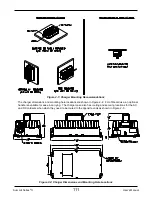
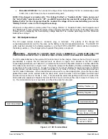
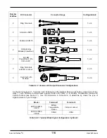
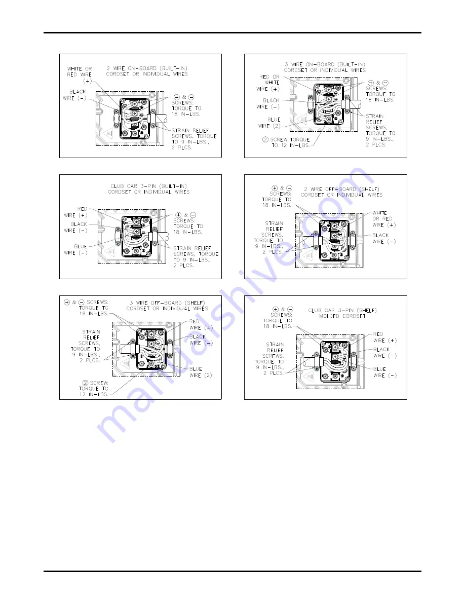
Figure 6.2-2: Common DC Terminal Block Configurations
7. VEHICLE LOCKOUT CONTROL
The charger lockout/interlock control signal can be interfaced with the vehicle/equipment to prevent
use/movement of the vehicle while the charger is in use. Depending on your model (see Table 6.2-2), the
lockout control is available on Terminal 2 of the DC terminal block (see Figure 6.2-1).
The charger's single-wire lockout control is typically interfaced to the vehicle motor speed controller. The
lockout signal can be configured to be pulled high to battery positive (+) or low to battery negative (-) when
the lockout is active using the "System Profile", which can be changed using the ChargerConnect app (see
Section 8). If you are uncertain of how to attach the lockout wiring, please contact your dealer.
If the charger is configured for on-board use, the lockout control will be active while AC power is applied to the
charger. If the charger is configured for off-board use, the lockout control will be active while a valid battery is
connected to the charger. Based on your application, you can configure the charger as on-board or off-board
via the ChargerConnect app under “System Profile” (see Section 8).
C o n fig u ra tio n 2
C o n fig u ra tio n 1
C o n fig u ra tio n 3
C o n fig u ra tio n 5
C o n fig u ra tio n 6
C o n fig u ra tio n 4
117
Summary of Contents for eNVy neighborhood vehicle
Page 1: ...OWNER S MANUAL 1 ...
Page 58: ...Service Record Number Date Hour Meter Reading Dealer Stamp 1 2 3 4 5 6 7 8 58 ...
Page 61: ...Golf Cart Battery Install Maintenance 61 ...
Page 71: ...OCV Open Circuit Voltage vs SOC State of Charge 71 ...
Page 92: ...92 ...
Page 94: ...94 ...
Page 96: ...96 ...
Page 128: ...Summit Series II User s Manual Represented By 43068 B 128 ...


