background image

Seating 

Danger: 

Remain seated at all times while the vehicle is being operated.

Do not attempt to carry more passengers than there are seats
on the vehicle.

Seat Removal and Replacement


Pull up on the rear of the seat and pull it up and to the rear to 
disengage the seat tabs. To install the seat, slide the seat tabs into 
the slots located at the front of the under-seat compartment. Push 
down firmly on the rear of the seat until the seat is in full contact 
with the seat base. 

Rear Facing Passenger Seats 

Danger: 

Remain seated at all times while the vehicle is being operated.

Do not place fingers or hands between the seat base and
cargo bed.

Exercise caution when mounting and dismounting the rear
step. Use the handholds for better stability.

26

Summary of Contents for eNVy neighborhood vehicle

Page 1: ...OWNER S MANUAL 1 ...

Page 2: ...D CONTROL AND ACCIDENT PREVENTION ARE DEPENDENT UPON THE AWARENESS CONCERN PRUDENCE AND PROPER TRAINING OF THE PERSONNEL INVOLVED IN THE OPERATION TRANSPORT MAINTENANCE AND STORAGE OF THE EQUIPMENT WARNING This manual provides procedures for minor maintenance but major repair information can be found in the eNVy Neighborhood Vehicle Service Manual Major repair should only be performed by an author...

Page 3: ...FEATURES CONTROLS AND OPERATION 14 CONTROL CENTER 14 IGNITION 15 BATTERY METER 22 SWITCHES 23 ELECTRICAL 24 PARKING BRAKE 24 DIRECTION SELECTION 25 SEATING 26 REAR FACING PASSENGER SEATS 26 TILT STEERING 27 HAULING CARGO 28 FLIP DOWN CARGO AREA 29 MAINTENANCE 30 SEVERE USE DEFINITION 30 ENVY LUBRICATION AND FLUID CHART 31 PERIODIC MAINTENANCE SCHEDULE 31 FUSE AND RELAYS 33 ...

Page 4: ...ERING 50 STORAGE 51 WASHING THE ENVY 51 STORAGE 52 TRANSPORTING THE ENVY 53 TOW PROCEDURE 54 ACCESSORIES 56 SPECIFICATIONS 57 SERVICE RECORD 58 OWNER S REFERENCE 59 PRE RIDE CHECKLIST 60 BATTERY INSTALL AND MAINTENANCE MANUAL 61 LESTER ELECTRICAL CHARGERCONNECT APP GUIDE 78 TABLE OF CONTENTS 79 SUMMIT SERIES II BATTERY CHARGER 101 TABLE OF CONTENTS 103 ...

Page 5: ...ctions in this manual can result in severe injury or death For any questions on material contained in this manual contact an authorized dealer for clarification Product Identification Number PIN Your machine s PIN can be found in two places The first location is under the hood just above the fuse and relay box The second location is in the battery compartment on the panel in front of the batteries...

Page 6: ...rdous situation that if not avoided may result in serious injury or death Warning Indicates a situation that if not avoided may result in property damage Notice Indicates a situation that could result in property damage Safety Safety Labels For your awareness warning labels are placed on the vehicle Read and follow the instructions on the vehicle carefully If any label becomes illegible or comes o...

Page 7: ... and when backing up Drive slowly while turning and do not make sudden stops Drive straight up and down sloped areas and do not operate on slopes greater than 14 25 Drive responsibly and do not allow children on the machine unattended or give them the start code Occupant capacity is two per bench seat Consult the owner s manual for maximum weight capacity Do not modify this vehicle to increase spe...

Page 8: ...es greater than 14 Remain seated and keep all limbs inside the vehicle during operation Never drive on public roads unless permitted by law General Safety Never Operate If you are under age 16 or without a valid driver s license At speeds too fast for your skills or conditions While under the influence of alcohol or drugs On hills 14 degrees or steeper With more passengers than seats With passenge...

Page 9: ... tires specified in this manual and maintain proper tire pressure as specified on safety labels Never modify this vehicle through improper installation or use of accessories Never exceed the stated load capacity for this vehicle Cargo should be properly distributed and securely attached Reduce speed and follow the instructions in this manual for hauling cargo and allow greater distance for braking...

Page 10: ...ator s risk of losing control Limit speeds to no more than the maximum speed on level ground Turning Improperly Turning improperly could cause loss of traction loss of control accident or overturn Never turn abruptly or at sharp angles Never turn at high speeds Never abruptly accelerate while turning Always make smooth controlled movements to complete safe turns Jumps and Stunts Attempting wheelie...

Page 11: ...aight downhill while applying light brake pressure to control speed Improper Tire Size Type or Maintenance Operating this vehicle with improper tire size or type will void the warranty See your dealer for details Operating this vehicle with uneven or low tire pressure could cause loss of control or accident Always use the size and type of tires specified for your vehicle Always maintain proper tir...

Page 12: ...eral Motor Vehicle Safety Standard 571 500 In these instances pursuant to Federal law the Distributor or Dealer MUST equip the product with headlights rear lights turn signals seat belts top horn and all other modifications for LSV s mandated in FMVSS 571 500 and affix a Vehicle Identification Number to the product in accordance with the requirements of FMVSS 571 565 Pursuant to FMVSS 571 500 and ...

Page 13: ... is charged in an area with at least five air exchanges per hour at a minimum Never charge a vehicle in an area where flames or sparks may be present Be especially careful of natural gas or propane water heaters and furnaces Always use a dedicated circuit for each battery charger Do not plug other appliances into the same receptacle as the charger during charging 13 ...

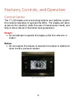
Page 14: ...eNVy The display will allow access to the machine notify the user of maintenance needs and help to show relevant information during operation Danger Do not attempt to operate the display while the vehicle is in motion Notice Do not expose the display to excessive moisture or attempt to clean it with a pressure washer Figure 2 eNVy Control Center 14 ...

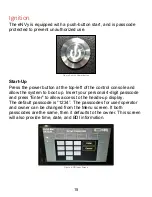
Page 15: ...trol console and allow the system to boot up Insert your personal 4 digit passcode and press Enter to allow access to the heads up display The default passcode is 1234 The passcodes for user operator and owner can be changed from the Menu screen If both passcodes are the same then it defaults to the owner This screen will also provide time date and BDI information Figure 4 PIN Input Screen 15 ...

Page 16: ...appear notifying the user that the passcode entry is disabled for 5 minutes The main screen will then appear and all touch functions are disabled After 5 minutes the user will be able to touch the message box to return to the passcode screen Reset Passcode Screen The reset passcode should be entered when first installing the display in the vehicle and should be printed in the manual or stored else...

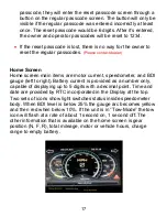
Page 17: ...main items are motor current speedometer and BDI gauge left to right Battery current is provided as a number only capable of displaying up to 5 digits with a decimal point Time and date are provided by RTC incorporated in the Display at the top Two sets of icons show light switches status inside speedometer body When BDI level is below 25 the gauge arc becomes yellow and then red when below 10 If ...

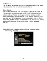
Page 18: ... and time eNVy logo color and vehicle settings Access to changes is restricted based on the passcode entered Vehicle settings units change passcode clock and date and eNVy logo color are only accessible with the Owner passcode The idle timeout can be set to 5 10 15min or off which will shut off the display if the vehicle is not moving or inputs detected Status Info is a multipage screen with the f...

Page 19: ... Motor Transaxle Oil Change Default Interval 600 miles 1200 miles after first reset Grease Suspension Joints Default Interval 100 hours Tires Check Tire Pressure Default Interval 20 hours 19 ...

Page 20: ... Battery Check Battery Terminals Default Interval 100 hours Check Battery Levels Default Interval 20 hours Faults 20 ...

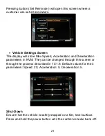
Page 21: ...cceleration and Deceleration parameters in NVM They canbe changed through this screen or through the process described in 10 1 9 Default values for the 3 parameters Speed 20 Acceleration 5 Deceleration 5 Shut Down Ensure that the vehicle is safely stopped on a flat level surface Press and hold the power button until the control console turns off 21 ...

Page 22: ...cle batteries are low and not allowed to charge for a sufficient period of time the battery meter may display an incorrect charge percentage When charging always allow enough time for the batteries to charge completely The battery discharge indicator BDI is an auxiliary gauge that displays the percentage of battery life remaining an hour meter and any error codes present 22 ...

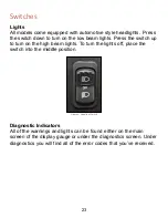
Page 23: ... to turn on the high beam lights To turn the lights off place the switch into the middle position Figure 5 Headlight Switch Diagnostic Indicators All of the warnings and lights can be found either on the main screen of the display gauge or under the diagnostics screen Under diagnostics you will find all of the error codes that you ve received 23 ...

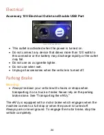
Page 24: ...se as a cigarette lighter Do not use when wet Unplug all accessories when the vehicle is turned off Parking Brake Warning Always tie down your vehicle with chains or straps when transporting it on a truck or trailer Never rely on the parking brake alone See Transporting the eNVy The eNVy is equipped with a motor brake which engages when the machine comes to a full stop or when the power is turned ...

Page 25: ...ction The eNVy is equipped with a direction selector switch at the bottom left of the control console Make sure to bring the vehicle to a complete stop before making a direction selection Press up on the rocker switch to shift into forward down for reverse and the middle setting will set the system to neutral which will engage the motor parking brake Figure 7 Shift Switch 25 ...

Page 26: ...abs To install the seat slide the seat tabs into the slots located at the front of the under seat compartment Push down firmly on the rear of the seat until the seat is in full contact with the seat base Rear Facing Passenger Seats Danger Remain seated at all times while the vehicle is being operated Do not place fingers or hands between the seat base and cargo bed Exercise caution when mounting a...

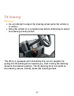
Page 27: ...tempting to adjust the steering wheel position Figure 8 Tilt Steering Adjustment Lever The eNVy is equipped with tilt steering that can be adjusted by pulling the tilt steering lever towards you then moving the steering wheel to the desired position The tilt steering lever is located on the steering column directly below the steering wheel 27 ...

Page 28: ...ver exceed the maximum weight capacity of the vehicle When determining the weight that you are adding to the vehicle include the weight of the operator passengers accessories cargo loads and the load on the trailer tongue The combined weight of these items must not exceed the maximum weight capacity Reduce speed and allow greater distances for braking when hauling cargo Always load the cargo box w...

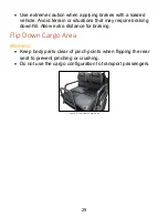
Page 29: ...ions that may require braking downhill Allow extra distance for braking Flip Down Cargo Area Warning Keep body parts clear of pinch points when flipping the rear seat to prevent pinching or crushing Do not use the cargo configuration to transport passengers Figure 9 Flip Down Cargo Bed 29 ...

Page 30: ...enuine eNVy parts available from your authorized eNVy dealer Maintenance intervals in the periodic maintenance chart are based upon average riding conditions Vehicles subject to severe use must be inspected and serviced more frequently Severe Use Definition Operation at extremely high or low temperatures Prolonged low speed heavy load operation Frequent or prolonged operation in dusty environments...

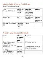
Page 31: ...ween min and max Maintain level between fill lines Transmission Gearbox Oil Valvoline SYN 75W 140 750 ml Periodic Maintenance Schedule Item Interval whichever comes first Remarks Clean motor battery charger and components of debris Pre ride Remove all debris Brake Fluid Pre ride Check level and pressure Adjust if necessary Steering Pre ride Front Suspension Pre ride Rear Suspension Pre ride 31 ...

Page 32: ...ssary Transmission Gearbox Oil 50hr 3 months Inspect level change yearly Front Rear Suspension 100hr 12 months Lubricate polyurethane joints Steering 150hr 12 months Inspect lubricate Throttle 150hr 12 months Inspect lubricate replace if necessary Wiring 250hr 24 months Inspect for wear apply dielectric grease to connectors subject to water mud etc Brake Fluid 500hr 24 months Replace fluid Front W...

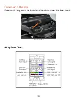
Page 33: ...Fuses and Relays Fuses and relays can be found in a fuse box under the front hood Figure 10 Fuse Block eNVy Fuse Chart 33 ...

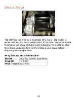
Page 34: ...ant but is not water proof If the motor should overheat the display will show a trouble code indicating the overheat Stop the vehicle and allow time for the motor to cool down before resuming vehicle operation eNVy Electric Motor Information Model 48V AC 5 0kW brushless Peak HP 14 8 HP Peak Torque 52 2 ft lb 34 ...

Page 35: ...two LEDs located on the controller have four different display modes indicating the type of information they are providing Controller LED Status Chart Display Status Action Neither LED illuminated Controller is not powered on or vehicle has dead battery or severe damage If machine will not turn on or turns on with this indicator contact an authorized dealer Yellow LED flashing Controller is operat...

Page 36: ...mage material and cause severe chemical burns Wear the appropriate protective attire and sufficient eye protection while working with batteries Batteries produce flammable hydrogen gas while charging Ensure that the charging area has sufficient ventilation and keep all sources of flame and spark away from the batteries There is a danger of electric shock when working with electricity Use insulated...

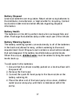
Page 37: ...all of the batteries in the bank and allows for easy uniform watering to the exact required level Each fill spout cover contains a small white indicator that will disappear if the battery level falls below optimal levels When this occurs distilled water must be added to bring the water levels back up To add water to the batteries 1 Ensure that the vehicle is safely parked on a level surface with t...

Page 38: ...city Deeply discharging the batteries will shorten their life span Discharged batteries can freeze in freezing temperatures Do not use charge or load test a frozen battery as it could explode Keep batteries fully charged when not in use If you observe ice in the cells or the case is swollen or split allow the battery to warm up before testing or charging Do not charge batteries at temperatures of ...

Page 39: ...h wireless communication which can be accessed using an Apple or Android smart phone tablet or similar device Download the ChargerConnect app for your device by scanning the QR code on the charger or visiting the App Store or the Google Play store and searching for ChargerConnect Notice Disconnecting and reconnecting the AC power supply cord will reset the charger Do not attempt to change the batt...

Page 40: ...charge the eNVy 1 Ensure that the vehicle is safely parked on a level surface with the switch off 2 Connect the power cord to an appropriate live AC outlet which is indicated by the blue AC PRESENT LED turning on The charger will start automatically as indicated by the yellow CHARGE STATUS LED beginning to blink slowly 3 If the charger must be disconnected from the battery while a charge cycle is ...

Page 41: ...The charger automatically terminates the charge cycle when the batteries reach full charge Which is indicated by either a The solid illumination of the green LED b The green LED beginning to blink slowly indicating a post charge phase 8 Before operating the eNVy disconnect the onboard charger AC power cord from the outlet 41 ...

Page 42: ... should be serviced and the charger reset by disconnecting the AC power supply for a minimum of 10 minutes before continuing another storage season LED Indicators The charger has four 4 LEDs to indicate charger status and fault information LED function is outlined below and in the following table AC Present blue Indicates charger is connected to a live AC inlet Fault red Indicates when a charger o...

Page 43: ...harge cycle phase constant current Not all charge profiles include a Finish phase Off Fast Blink Balance Equalize phase An extended charge cycle is occurring because a trigger condition has been met cycle count etc Not all charge profiles include a Balance Equalize phase Off Solid On Charge cycle complete Off Slow Blink Charge cycle complete Post Charge phase constant voltage float etc Not all cha...

Page 44: ... Blink Off Solid On Over Temp Maximum temperature was met Charge cycle was halted and will restart when the temperature decreases Slow Blink Fast Blink Slow Blink Low Temp Temperature is too low to start a charge cycle 25 C Charging will start when temperature increases Slow Blink Solid On Off Low DC DC battery voltage is too low to start charging 10V Slow Blink Off Off No AC AC power was lost dur...

Page 45: ...Blink Slow Blink Solid On Hardware Fault Contact dealer Fast Blink N A N A Hardware Fault Contact dealer Unit is still able to charge Battery Solid On Off Off Phase A fault condition most commonly maximum time was met during a particular charge cycle phase start bulk plateau absorption finish etc Solid On Off Slow Blink Max Voltage Maximum voltage was met Solid On Off Solid On Min Voltage Minimum ...

Page 46: ...cal accessories such as lights can be added with no modification to the electronics system Transmission Gearbox Check and change the transmission oil at the intervals outlined in the Periodic Maintenance Chart Refer to the lubrication and fluid recommendations chart for type and capacity Oil Check To check the Transmission Gearbox oil 1 Ensure that the vehicle is safely parked on a flat surface 2 ...

Page 47: ...n plug 5 Add the recommended oil to the appropriate level 6 Reinstall the check fill plug 7 Inspect for leaks Vehicle Submerged in Water Notice If your vehicle becomes immersed in water major motor damage can result Intimidator warranty does not cover vehicles submerged in water If your vehicle does become submerged above the electric motor thorough inspection is necessary It is recommended that y...

Page 48: ... or any time the fluid becomes contaminated To change the brake fluid 1 Ensure that the vehicle is safely parked on a flat surface 2 Inspect the brake fluid level at the reservoir located in the driver s side wheel well The level should be between the MAX and MIN indicator lines 3 If the fluid level is low remove the cap and fill until the fluid level falls between the indicators 4 Reinstall the c...

Page 49: ... non standard tires use of oversized tires or use of different tread patterns can change or impair the handling of the vehicle and result in severe injury Tire construction characteristics and inflation pressure can greatly influence vehicle handling Intimidator recommends that you replace tires with standard OEM tires It is also important that all tires on the machine are of the same type and hei...

Page 50: ...iodic maintenance chart To inspect the steering wheel 1 Ensure that the vehicle is safely parked on a flat surface 2 Lightly turn the steering wheel left and right There should be no more than 1 of free play 3 If there is excessive free play strange noises or the steering feels rough have the steering system inspected by an authorized dealer 50 ...

Page 51: ...vehicle s seat and plastic Immediately wash mud off of the vehicle with mild soap and water Keeping your vehicle clean will not only improve its appearance but it can also extend the life of various components Below are some guidelines for keeping your eNVy clean Avoid the use of harsh or abrasive cleaners that can scratch the finish Use automotive adhesive remover to clean sticker residue from pl...

Page 52: ...portant to regularly check on the vehicle to ensure that there are no charging electrical issues 4 Put a cover over the vehicle to keep dust and dirt from collecting and to discourage small animals from taking up residence Do not leave the battery charger plugged in when covered Remove the cover to charge the batteries Removal from Storage 1 Remove the cover 2 Clean the battery terminals charge th...

Page 53: ...s to load it onto a trailer or flatbed truck Below are some considerations while transporting your machine Use extra caution with any and all activities involved with loading securing transporting and unloading your machine Make sure that the trailer truck is parked safely on flat ground and that the tires are immobilized Do not use a ramp at an angle of more than 14 degrees Use extra care when dr...

Page 54: ...ing procedures outlined below The procedure for towing the eNVy will vary depending on the state of charge within the batteries To tow an eNVy with battery charge 1 Safely attach a sufficiently rated tow strap to a secure location on the eNVy frame Figure 12 Front Tow Attachment Points Figure 13 Rear Tow Attachment Point 54 ...

Page 55: ...ed location 6 Return the tow switch to the RUN position to complete towing and turn the machine off To tow an eNVy with NO battery charge 1 Safely attach a sufficiently rated tow strap to a secure location on the eNVy frame 2 Remove the seat to access the battery compartment 3 Remove the cap of the two pin Deutsch connector located near the controller and attach the off board jump pack sold separa...

Page 56: ...Accessories For a complete line of genuine eNVy accessories visit www baddawgaccessories com 56 ...

Page 57: ...ar Bumper to Bumper DRIVE SYSTEM Motor 48 Volt Brushless Battery System Four 12V Deep Cycle Lead Acid Batteries with Included Watering Kit Charging System On Board Charging System Torque Peak 52 2 ft lb Max Horsepower 6 7 hp 5 kW Max Speed 20 mph MEASUREMENTS Weight 1 389 lb 630 0 kg Length 124 315 0 cm Width 55 139 7 cm Height 78 198 1 cm Turning Radius 115 292 1 cm Wheelbase 69 175 3 cm Frame Cl...

Page 58: ...Service Record Number Date Hour Meter Reading Dealer Stamp 1 2 3 4 5 6 7 8 58 ...

Page 59: ...Owner s Reference Keep original copy on file at your dealership VIN PIN Model Date of Purchase Dealer Last Name owner First Name owner Address City State Postal Code Day Phone Evening Phone 59 ...

Page 60: ...e pedals operate smoothly o Ensure proper brake and parking brake operation o Ensure that the gear selector operates properly Lights o Make sure lights high and low beams operate properly as well as brake lights Fluids o Differential Oil check level and condition o Leaks inspect inside and underneath the machine for evidence of fluid leaks Chassis and Accessories o Ensure all shocks fasteners and ...

Page 61: ...Golf Cart Battery Install Maintenance 61 ...

Page 62: ...llel Connections Series Parallel Connections Charging Your Batteries Proper Maintenance Temperature Compensation Torque Specifications Cleaning Addition of Water distilled or deionized only Tips Cleaning Storing your Batteries Taking Care of You Batteries 62 ...

Page 63: ...a medical professional Ensure connectors are torqued to the proper specifications see fig 1 illustration for proper specs Do not lay anything on top of the batteries wires cables tools etc Always charge and handle batteries in a well ventilated area Only add distilled or deionized water to your batteries and fill to the appropriate level Never add pre mixed acid to your batteries 5 16 Studs or Bol...

Page 64: ... Series 6v Parallel 12v Positive side of charger Negative side of charger 6v Series connection 12v 12v 12v To Charger Positive or to Inverter Positive To Charger Ground or to Inverter Ground 12v Parallel connection 12v 64 ...

Page 65: ...Side of Charger or Inverter 6V 6V 6V 6V Series connection increase voltage Parallel connection increase capacity 12v 12v Positive side of charger Negative side of charger 12v Series Parallel connection 24v 12v 12v To Positive Side of Charger or Inverter 65 ...

Page 66: ...To Negative side of charger To Positive side of charger 8 Battery Connection using 6V Batteries For 48v System Series Connection 66 ...

Page 67: ...To Negative side of charger To Positive side of charger 6 Battery Connection using 8V Batteries For 48v System Series Connection 67 ...

Page 68: ...To Negative side of charger To Positive side of charger 6 Battery Connection using 6V Batteries For 36v System Series Connection 68 ...

Page 69: ...0 59 30 Absorption Taper to 3 of 20 hr Ah Rating and hold for 2 3 hours 2 47 7 40 14 80 29 60 59 30 Float 2 25 6 75 13 5 27 00 54 00 Equalization Total time 2 hrs 2 70 8 10 16 20 31 20 62 40 Charging State Current Amps Voltage Regulation Note Leave vent caps securely fastened while doing any charging 69 ...

Page 70: ...rging voltage is 14 8 6 cells 7 degrees below 0 0028 14 92 volts 5 A 12 volt battery 21º C The recommended charging voltage at 25º C is 14 8 volts The adjusted charging voltage is 14 8 6 cells 4 degrees below 0 005 14 92 volts 6 For every 1º F above 77º F subtract 0 0028 volts per cell or for every 1º C above 25º C subtract 0 005 volts per cell to the charger voltage setting 7 A 12 volt battery 85...

Page 71: ...OCV Open Circuit Voltage vs SOC State of Charge 71 ...

Page 72: ...efore you add water Only add water to discharged or partially discharged batteries before charging if the water levels are below the plates Once fully charged continue with the watering procedure When adding distilled or deionized water fill to the appropriate level and never overfill After adding water secure vent caps back on batteries 72 ...

Page 73: ... terminals and connections with a cloth or brush and a sodium bicarbonate solution 1 cup of baking soda to 1 gallon of water 150g 1L Do not allow the cleaning solution to get inside the battery Rinse with water and dry with a clean cloth Keep the area around batteries clean and dry After connections are clean and dry reconnect the cables and or hardware Apply a spray protector or equivalent to the...

Page 74: ...e during storage Monitor the specific gravity or voltage every 4 6 weeks In high temperatures greater than 90 F or 32 C monitor the specific gravity or voltage every 2 4 weeks as batteries will self discharge faster Stored batteries should be given a boost charge when they are at or less than 70 State of Charge SOC After storage recharge before use 74 ...

Page 75: ...ves into each cell going all the way across one row before starting on the next row Make sure floats clear any obstruction in vent well 4 Once the system is installed fully charge the batteries Immediately following full charge water the batteries Remove vent caps Fully Assembled Kit GEZ48 KITBC GYM KITC29BC This is a typical battery vent opening MAX LEVEL This is a special battery vent opening 1 ...

Page 76: ...e levels inside the battery rise during the charging cycle and fall during the discharge cycle Adhere to the following operating requirements when using the direct fill link Inlet pressure range is 10 90 PSI Air should be purged from the hose line before filling Simply run water through the hose before connecting the direct fill link to the hose end Batteries need to be watered every 2 4 weeks dep...

Page 77: ...oss 2 Insert the pump assembly end into a just of distilled water 3 Remove the dust cap from the watering system fill tube Connect it to the manual pump connector by inserting it into the quick connect 4 Squeeze the bulb on the manual pump to begin filling the battery cells with water When the bulb becomes hard and the valve indicator eyes have risen all of the cells are full 5 Disconnect the manu...

Page 78: ...Page 1 of 23 Lester Electrical ChargerConnect App Users Guide For use with Summit Series II battery chargers 78 ...

Page 79: ...1 12 13 18 20 21 TABLE OF CONTENTS Sections Introduction Dashboard Navigation Menu Diagnostics History System Information System Profile Auto Voltage Mode Battery Profile Battery Profile Selector Utilities Offline Mode 22 79 ...

Page 80: ...th The ChargerConnect application app requires both the Bluetooth and location services to be enabled on the mobile device for proper operation Once the charger is connected to a valid battery pack open the ChargerConnect app and select the charger s serial number from the list of available chargers listed If the serial number of your charger is not listed touch the Refresh bar to re scan for avai...

Page 81: ...attery profile A description of this profile including the compatible batteries is available on the Battery Profile screen System Profile Displays the profile number of the active system profile the setup file used to configure the battery charger to the application LED Display Displays the same charge status LEDs that are present on the charger Details regarding the LEDs can be found in the charg...

Page 82: ...uto Voltage Mode is active this field displays the detected battery pack voltage once the proprietary algorithm mentioned in the Auto Battery Voltage Detection reaches 100 completion Manual Stop Start Button Tapping this button will stop a charge cycle red button or start a charge cycle green button Manual Equalize Balance Button If the active battery profile includes an Equalize or Balance phase ...

Page 83: ...connects the Bluetooth connection between the charger and your smart phone or tablet device and returns you to the Connect screen Note If the connected charger is actively charging the History System Profile Battery Profile and Utilities menu items will be disabled The Manual Stop Start Button on the Dashboard screen can be used to 1 stop the active charge cycle in order to access these menu items...

Page 84: ...ed charge time remaining in minutes Phase Displays the active charge cycle phase Amp Hours Charged Displays the number of amp hours charged Fault Displays any active faults Descriptions of the faults as well as instructions for resolving them are detailed in the charger user s manual AC Volts Displays the AC input voltage in volts Battery Temperature Displays the battery temperature in C if a batt...

Page 85: ...e history records that have been downloaded from the connected charger and uploaded to the ChargerConnect Cloud Last Charge Cycle Number of the last charge cycle history record that has been downloaded from the connected charger and uploaded to the ChargerConnect Cloud Get 10 Records Button Tap to download the latest 10 charge cycle history records that have not been previously downloaded from the...

Page 86: ...w section below the selection buttons Press the blue arrow key to view the History Details screen This area displays the data for an individual charge cycle history record When you have finished reviewing the data you can use the Back button found at top left of history screen in order to return to the Charger Histories tab 86 ...

Page 87: ...een downloaded from the connected charger to your smart phone or tablet device to the ChargerConnect Cloud Once the records have been uploaded they can be accessed from any smart phone tablet laptop or PC via ChargerConnect net using the charger serial number ChargerConnect net will require a user account to be setup to view the registered information Data uploaded and registered to the cloud serv...

Page 88: ... version of charge control firmware on the connected charger Power Control Version Displays the version of power control firmware on the connected charger Hardware Version Displays the hardware version of the connected charger Vehicle ID Displays the ID of the vehicle that is paired with the charger if applicable The Vehicle ID is factory set to be blank The Vehicle ID can be set modified on the D...

Page 89: ...hecked for Off Board On Board chargers are designed to be mounted on electric vehicles equipment While the DC output is connected to a battery pack of the proper voltage a charge cycle automatically starts when the AC input plug is connected to AC power unless a safety period of time has not passed since the successful completion of the previous charge cycle Disconnecting the DC output from the ba...

Page 90: ...app screenshots on following page Select Summit Series II charger models support automatic multi voltage DC charging referred to as Auto Voltage Mode Auto Voltage Mode provides automatic DC output voltage detection and adjustment so that battery packs of nominal 48V and 36V 650W 48V 36V and 48 36V models or nominal 48V 36V and 24V all 1050W models can be charged with a single charger without any c...

Page 91: ...ery pack This mode is primarily used when the charger will be charging 48V 36V and 24V nominal battery packs or any combination of two 2 of these voltages where the battery packs are of different types and or capacities so using the Scalable Profile mode is not appropriate All voltage must be assigned a battery profile for this mode to be used SCALABLE PROFILE o 650W 48V 36V and 48 36V models the ...

Page 92: ...92 ...

Page 93: ...ons provide detailed descriptions of the system profiles Delete system profiles that reside on your smart phone or tablet device via the red trash can button Cloud Profiles Tab Lists all system profiles available for download from the ChargerConnect Cloud Download system profiles from the Cloud to your smart phone or tablet device via the green arrow buttons Blue question mark buttons provide deta...

Page 94: ...94 ...

Page 95: ...local battery profiles are stored in Slots which are numbered 0 19 You can either select an empty Slot to store the battery profile that will be uploaded to the charger or a Slot that currently contains a battery profile in which case the battery profile will be overwritten o NOTE When a battery profile is uploaded to the connected charger it automatically becomes the Active profile on the charger...

Page 96: ...96 ...

Page 97: ... of the vehicle batteries If your brand is not listed select other Touch the down arrow next to the System Voltage and choose the voltage of the vehicle Touch the Submit button to send your battery information to the database Touch the down arrow next to the Battery Model and choose the model of the batteries The Charger Model will automatically populate touch the submit button to view the recomme...

Page 98: ... located in the Download folder of the Device phone tablet iOS The battery profile text file name must be LesterElectricalBatteryProfile txt and located in the ChargerConnect NoCloud folder in the Device s phone tablet File System The battery profile text file name must be LesterElectricalSystemProfile txt and located in the ChargerConnect NoCloud folder in the Device s phone tablet File System If...

Page 99: ...s from chargers in a location where your smart device does not have Internet access You can use Utilities to upload these charge cycle history records to the ChargerConnect Cloud at a later time when your device does have Internet access Profile Selector is also available in Utilities by clicking on green Profile Selector button Once in this option the Offline Battery Profile Selector will appear ...

Page 100: ...names are those of their respective owners Apple is a trademark of Apple Inc registered in the U S and other countries App Store is a service mark of Apple Inc registered in the U S and other countries Android is a trademark of Google Inc Google Play and the Google Play logo are trademarks of Google Inc Copyright Lester Electrical of Nebraska Inc All rights reserved 43047 B 100 ...

Page 101: ...1050W VERSION V2 SWITCH MODE INDUSTRIAL BATTERY CHARGER USER S MANUAL Important Safety Installation Operation and Maintenance Instructions www LesterElectrical com 101 ...

Page 102: ...ck of a different type or capacity use the ChargerConnect app to verify that the proper active battery profile is selected see Section 8 One of two styles of ratings label will be attached to your charger Examples of both styles are shown below Please fill in the applicable blank label below with the information from the ratings label on your charger for future reference CAUTION PRIOR TO OPERATING...

Page 103: ...argers 13 5 AC INPUT 13 6 DC OUTPUT 14 6 1 Auto Voltage Mode 14 6 2 DC Output Cordset 15 7 VEHICLE LOCKOUT CONTROL 17 8 BLUETOOTH WIRELESS 18 9 EXTERNAL PORT 19 10 PROPER CARE OF DEEP CYCLE LEAD ACID MOTIVE POWER BATTERIES 19 10 1 Personal Safety Precautions 20 11 CHARGER OPERATION 20 11 1 Off Board Charger Operation 21 11 2 On Board Charger Operation 22 11 3 Storage Mode Operation 22 12 LED INDIC...

Page 104: ...ER DOES NOT REDUCE THIS RISK 7 DANGER RISK OF ELECTRIC SHOCK DO NOT TOUCH UNINSULATED PORTION OF AC OR DC CONNECTORS OR UNINSULATED BATTERY TERMINAL 8 DANGER RISQUE DE CHOCKS ÉLECTRIQUES NE PAS TOUCHER LES PARTIES NON ISOLÉES DU CONNECTEUR DE SORTI OU LES BORNES NON ISOLÉES DE L ACCUMULATEUR 9 CAUTION CHARGE ONLY BATTERIES OF THE SAME TYPE VOLTAGE CELL NUMBER AND AMP HOUR CAPACITIES AS SHOWN ON TH...

Page 105: ...PLACE 16 WARNING LEAD ACID BATTERIES CONTAIN SULFURIC ACID WHICH MAY CAUSE BURNS DO NOT GET ACID IN EYES ON SKIN OR CLOTHING IF CONTACT WITH THE EYES OCCURS FLUSH IMMEDIATELY WITH CLEAN WATER FOR 15 MINUTES AND OBTAIN MEDICAL ATTENTION 17 WARNING ONLY A QUALIFIED SERVICE TECHNICIAN SHOULD PROGRAM OR SERVICE THIS EQUIPMENT 18 CAUTION DO NOT OPERATE THE CHARGER IF IT HAS RECEIVED A SHARP BLOW BEEN D...

Page 106: ...T BRENNBAREM MATERIAL WIE ZIEGELN BETON ODER METALL 6 GEFAHR STROMSCHLAGGEFAHR TRENNEN SIE DAS LADEGERÁT VOR DER WARTUNG VON DER BATTERIE UND NETZSTROM DAS AUSSCHALTEN DES LADEGERÄTS VERRINGERT DIESES RISIKO NICHT 7 GEFAHR STROMSCHLAGGEFAHR BERÜHREN SIE NICHT DEN UNINSULIERTEN TEIL VON AC ODER DC ANSCHLÜSSEN ODER UNINSULIERTEN BATTERIEANSCHLUSS 9 ACHTUNG LADEN SIE NUR BATTERIEN DER GLEICHEN ART SP...

Page 107: ...IEN ENTHALTEN SCHWEFELSÄURE WELCHE VERBRENNUNGEN VERURSACHEN KANN VERMEIDEN SIE KONTAKT MIT DEN AUGEN DER HAUT ODER DER KLEIDUNG MIT DER SÄURE FALLS ES KONTAKT MIT DEN AUGEN GEBEN SOLLTE SPÜLEN SIE DEN AUGEN SOFORT 15 MINUTEN LANG MIT REINEM WASSER UND SUCHEN SIE EINEN ARZT AUF 17 ACHTUNG NUR EIN QUALIFIZIERTER SERVICE TECHNIKER SOLLTE DIESES GERÄT PROGRAMMIEREN ODER SERVISIEREN 18 ACHTUNG BETREIB...

Page 108: ...DÉCHARGE ÉLECTRIQUE DÉBRANCHEZ LE CHARGEUR DE LA BATTERIE ET DU COURANT ALTERNATIF AVANT L ENTRETIEN L ARRÊT DU CHARGEỦR NE RÉDUISANT POINT CE RISQUE 7 DANGER RISQUE DE DÉCHARGE ÉLECTRIQUE NE TOUCHEZ PAS LES PARTIES NON ISOLÉES DES CONNECTEURS AC OU DC OU LE BORNE NON ISOLÉ DE LA BATTERIE 9 ATTENTION NE CHARGEZ SEULEMENT QUE LES BATTERIES DU MÊME TYPE TENSION NOMBRE DE CELLULES ET CAPACITÉ AMP HEU...

Page 109: ...AIN DE CHARGER DANS UN ENDROIT FERMÉ 16 AVERTISSEMENT LES BATTERIES PLOMB ACIDE CONTIENNENT DE L ACIDE SULFURIQUE QUI PEUT CAUSER DES BRÛLURES N ATTRAPEZ PAS L ACIDE DANS LES YEUX NI SUR LA PEAU NI SUR LES VÊTEMENTS EN CAS DE CONTACT AVEC LES YEUX RINCEZ IMMÉDIATEMENT AVEC DE L EAU PROPRE PENDANT 15 MINUTES PUIS ACCEDER AUXSOINS MÉDICAUX 17 AVERTISSEMENT SEUL UN TECHNICIEN DE SERVICE QUALIFIÉ POUR...

Page 110: ...e ChargerConnect app to verify that the proper active battery profile is selected and that the system settings match your application see Section 8 CAUTION PRIOR TO OPERATING THE CHARGER VERIFY THAT THE ACTIVE BATTERY PROFILE MATCHES THE BATTERIES IN YOUR EQUIPMENT AND THAT THE SYSTEM SETTINGS MATCH YOUR APPLICATION BY USING A SMART PHONE OR TABLET AND THE CHARGERCONNECT APP AS DESCRIBED IN SECTIO...

Page 111: ...ions are shown in Figure 2 2 For off board use an optional handle is available for ease in carrying The charger case also has routing and securing locations for the AC and DC cordsets when when they need to be routed to the opposite ends as shown in Figure 2 3 Figure 2 2 Charger Dimensions and Mounting Hole Locations 111 ...

Page 112: ... additional details If the active battery profile is changed mark the charger ratings label or add an additional label or tag CAUTION THIS CHARGER IS FOR USE ONLY WITH BATTERY SYSTEMS OF THE SAME TYPE AS THE ACTIVE BATTERY PROFILE BATTERIES IMPROPERLY MATCHED WITH THE CHARGER MAY BURST CAUSING PERSONAL INJURY AND DAMAGE TO THE BATTERIES OR CHARGER Battery manufacturers frequently use the same batt...

Page 113: ...ss a safety period of time has not passed since the successful completion of the previous charge cycle Disconnecting the DC output from the battery pack IS NOT REQUIRED to automatically start a new charge cycle 5 AC INPUT CAUTION TO REDUCE THE RISK OF ELECTRIC SHOCK OR FIRE DISCONNECT AC POWER FROM THE CHARGER BEFORE INSTALLING OR REMOVING UNIT The charger has an AC input rating of 100 240 volts 5...

Page 114: ...OM THE BATTERIES KEEP SPARKS FLAME AND SMOKING MATERIALS AWAY FROM BATTERIES TO REDUCE THE RISK OF FIRE DO NOT USE THE CHARGER NEAR FLAMMABLE MATERIALS OR VAPORS Only charge batteries of the same type voltage number of cells and amp hour capacities listed on the charger ratings label Before 1 using the charger for the first time or 2 using the charger with a battery pack of a different type or cap...

Page 115: ...d WARNING CHARGER DC CORDSET MUST HAVE A MINIMUM OF 12AWG WIRE SIZE FOR PROPER HEAT DISSIPATION TO PREVENT RISK OF FIRE DO NOT USE SMALLER GAUGE WIRE The DC cordset attaches to the external DC terminal block on the charger Remove the touch proof cover if pre installed to expose the DC terminal block as shown in Figure 6 2 1 Based on the DC cordset connector plug terminals use Table 6 2 1 to determ...

Page 116: ... Output Connector Configurations As shown in Figure 6 2 1 Terminal 1 and Terminal 2 on the terminal block can be factory ordered one of two ways 1 with CANbus communication signals CANH and CANL or 2 Battery Temperature Sense and Vehicle Lockout see Section 7 Use the information in Table 6 2 2 to determine by model the type of signals present on your charger Model Terminal 1 Terminal 2 28750 29410...

Page 117: ...itive or low to battery negative when the lockout is active using the System Profile which can be changed using the ChargerConnect app see Section 8 If you are uncertain of how to attach the lockout wiring please contact your dealer If the charger is configured for on board use the lockout control will be active while AC power is applied to the charger If the charger is configured for off board us...

Page 118: ...ge Battery Temperature if a sensor is present History of charge cycle data o Charger Histories tab Overview Charger Total Charge Cycles Total Amp Hours Device Total Charge Cycles Last Charge Cycle Cloud Total Charge Cycles Last Charge Cycle Get 10 Records button Get All Records button Delete All Records button Records section where individual records that have been downloaded from the charger can ...

Page 119: ...visible an optional remote LED cable assembly can be used Attach the remote LED cable assembly to the external port on the charger and hand tighten the connector mounting screws The LED end of the cable assembly is to be rear mounted through a hole on the vehicle or it can be attached to a panel which mounts to the vehicle Install the remote LED assembly as shown and attach the accompanying decal ...

Page 120: ...gs as specified in this manual on the charger in the battery manuals and in the vehicle manuals 10 1 Personal Safety Precautions 1 Have someone within the range of your voice and close enough to quickly come to your aid when you work near a lead acid battery 2 Ensure ample fresh water and soap are nearby in case battery acid contacts your skin clothing or eyes 3 Wear complete eye and clothing prot...

Page 121: ... power cord to an appropriate AC outlet if not already connected and the blue AC PRESENT LED will turn on 2 Connect the charger DC output connector plug to the battery connector receptacle The charger will start automatically which is indicated by the yellow CHARGE STATUS LED beginning to blink slowly 3 If the charger must be disconnected from the battery while a charge cycle is in progress first ...

Page 122: ...eginning to blink quickly Not all charge profiles include a Balance Equalize phase 8 The charger automatically terminates the charge cycle when a battery reaches full charge which is indicated by 1 the solid illumination of the green LED or 2 the green LED beginning to blink slowly indicating a post charge phase The required charge time is affected by numerous factors including battery amp hour ca...

Page 123: ...ed LED CHARGE STATUS Yellow LED CHARGE COMPLETE Green LED DESCRIPTION Solid On Solid On Solid On LED check for a few seconds during charger initialization Slow Blink Off Bulk Start charge cycle phase constant power or constant current Fast Blink Off Absorption Plateau charge cycle phase constant voltage Greater than 80 charged Solid On Off Finish charge cycle phase constant current Not all charge ...

Page 124: ...ing Charge cycle was halted and will restart when AC power returns Slow Blink Solid On Slow Blink HARDWARE FAULT Contact Lester Electrical Slow Blink Slow Blink Off HARDWARE FAULT Contact Lester Electrical Slow Blink Slow Blink Slow Blink COMM FAULT LEDs blink one at a time in a rotating pattern Contact Lester Electrical Unit is still able to charge Slow Blink Slow Blink Solid On HARDWARE FAULT Co...

Page 125: ...cessfully when an extended Balance Equalize charge cycle phase is active or when a post charge phase is active FAULT Red LED CHARGE STATUS Amber LED CHARGE COMPLETE Green LED Description Solid On LED check for a few seconds during charger initialization Solid On and then Off Slow Blink Bulk Start charge cycle phase constant power or constant current Fast Blink Absorption Plateau charge cycle phase...

Page 126: ...ially reduced by returning temporarily to daily charging 3 A decrease in vehicle equipment range where the battery loses power faster indicates one of the following conditions a The electrolyte level in a wet lead acid battery was allowed to drop below the top of the battery plates If so add distilled water to just cover the top of the plates immediately upon discovery and then fill to the proper ...

Page 127: ...4S 2 Wire 12AWG 9ft DC Cordset with Lester 2 blade Gray Molded Plug 41891S 3 Wire 2 12AWG 1 16AWG 3ft DC Cordset with Ring Terminals LO 41878S 3 Wire 2 12AWG 1 16AWG 6ft DC Cordset with Ring Terminals LO 41879S 48V Model 28750 28760 and 24 48V Model 30410 30420 Description Lester Part Number 3 Wire 12AWG 9ft DC Cordset with 48V CCI Gray Molded Plug 41892S 3 Wire 12AWG 12ft DC Cordset with 48V CCI ...

Page 128: ...Summit Series II User s Manual Represented By 43068 B 128 ...

Reviews: