background image


INDUSTRIAL SHREDDER 

Instruction manual for use and maintenance 


MSM0005EN_

F


21 / 90 


2.6 

RISKS, PROTECTIONS, WARNINGS AND NOTICES 

2.6.1


General Safety 

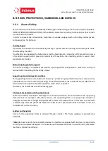
The machine which has been installed by following the indications given in this manual (see Chapter 4 

INSTRUCTIONS FOR INSTALLATION) and handled by operators according to these instructions cannot 

be the cause of accidents. 
In order to prevent risks of accidents, machines are usually equipped with such safety devices (active 

and passive) as, for instance: 
 

Feeding hopper 

It prevents the operator from accidentally coming in contact with the moving mechanical parts inside 

the shredding chamber. 
The shredder is supplied with a bolted cover and the feeding inlet is closed by a PVC protection (in case 

of standard hopper), which prevents material fly off caused by the shredding action in case of hard 

material to be treated. 
 

Motor coupling protection guard 

The motor coupling is completely enclosed by a plate guard for the operators’ protection. It may be 

removed after loosening the fastening screws. 
 

Supporting stand closing grids and door 

The supporting stand is surrounded and closed by a protection grid, which is fixed on 3 sides and has 

openable doors on the fourth side (loading). The interlocked safety micro switches are installed on the 

doors, which interrupt the shredder operation when they are opened. 
The safety micro switches are of the locking type. 
 

Photocells for detection of the collection bin 

When the material shredded is discharged in a movable collection bin and therefore the supporting 

frame cannot be equipped with safety fences, the supporting frame is equipped (or should be 

equipped at customer’s charge) with photocells to detect the collection bin. In this case, the shredder 

is started only after the photocells detect the collection bin positioned under the frame. If not, the 

shredder will not start running. 
 

Ladders and handrails 

Access to the supporting frame is allowed through a ladder. The frame walkway is protected  by 

handrails.  
 

Table 2-1 

shows a list of the main safety devices the machine is equipped with. End user is responsible 

to verify and complete all aspects in connection with equipment safety in case of partly completed 

machinery (almost machinery). 


Summary of Contents for HDD Gladiator

Page 1: ...lted and therefore should be kept nearby the shredder in a clearly visible position and protected by a cover aimed at preventing it from deteriorating All data and illustrations contained herein inclu...

Page 2: ...n See typeplate Blades assembly 5 blades 1 hook 28 5 mm thickness and 11 blades 11 hooks 12 mm thickness Motor speed 1 500rpm 4poles 400V 50Hz 1 200rpm 6poles 220V 60Hz Shredding chamber General lay o...

Page 3: ...for use and maintenance MSM0005EN_F 3 90 Table 1 2 Objects to be supplied Objects of this supply Industrial shredder mod HDD GLADIATOR s n 5557xx Electric switchboard with control panel 2021 Feeding h...

Page 4: ...8 PERSONAL PROTECTION EQUIPMENT B 23 09 2020 Updated all machine series names with HHD GLADIATOR D 21 12 2020 Updated chapters 1 2 and 4 related to the parts common to all series E 02 03 2021 Deleted...

Page 5: ...talled 26 2 6 3 Residual risks 27 2 6 3 1 During the normal running operations 27 2 6 3 2 During the routine maintenance 27 2 6 4 Warning and accident prevention plates 28 2 7 PREARRANGEMENTS FOR INST...

Page 6: ...OLLER PLC 61 5 4 ELECTRICAL TESTS ON THE SHREDDER 62 6 SHREDDER OPERATION 64 6 1 SHREDDER START 64 6 1 1 Operation and alarm controls and indicators 64 6 2 STARTING SEQUENCE 67 6 2 1 Vessel substituti...

Page 7: ...des pack 77 7 3 3 Motion tests except 4S series 79 7 3 4 Final settings 79 7 3 5 Replacing lubricating oils 80 7 3 6 Gears lubrication for series HDD GLADIATOR 80 7 3 7 Lubrication with grease of the...

Page 8: ...9 Figure 3 3 Chamber for series HDD GLADIATOR 41 Figure 3 4 Motor drive for series HDD GLADIATOR 42 Figure 4 1 Discharge from the machine 47 Figure 4 2 How to lift the shredding chamber for series HDD...

Page 9: ...ion equipment for operators assigned to use 32 Table 2 6 Personal protection equipment for maintenance technicians 33 Table 3 1 Weights kg Typical 44 Table 3 2 Dimensions cm Typical 44 Table 3 3 Level...

Page 10: ...INDUSTRIAL SHREDDER Instruction manual for use and maintenance MSM0005EN_F 10 90 This page is left intentionally blank...

Page 11: ...hich sums up any possible operating problems which could occur according to the manufacturer s experience and indications on how to reset the machine should such problems crop up It is not necessary t...

Page 12: ...s delivered and accepted The guarantee is cancelled also when the user carries out an improper use of the machine or does not follow the instructions for the assembly correct use and maintenance writt...

Page 13: ...s instructions 1 7 CONVENTIONAL GRAPHICS AND GLOSSARY The following graphic elements along with emphasized text are used in the manual to make important notices and instructions immediately visible DA...

Page 14: ...different heights according to the type of material to be treated SPACERS rings installed on blade shafts to space out the blades and of a similar thickness to the latter CLEANING SECTORS components...

Page 15: ...ure levels at a work station and at other specified positions Engineering method in an essentially free field over a reflecting plane UNI EN 12012 3 2008 Rubber and plastics machines Size reduction ma...

Page 16: ...INDUSTRIAL SHREDDER Instruction manual for use and maintenance MSM0005EN_F 16 90 This page is left intentionally blank...

Page 17: ...operly and is therefore compelled to make certain that his personnel have read and understood the contents The unauthorized tampering or substitution of one or more machine parts the use of accessorie...

Page 18: ...ctive safety devices micro switches interlocks etc the check for consistency and correct positioning of the safety guards protection plates protection grids etc DANGER The shredder cannot be installed...

Page 19: ...using an iron separator DANGER Material partially coming out of the hopper should not be let into the loading inlet in particular filaments tapes or films partially engaged by the shredder and dragged...

Page 20: ...lammable liquids and gases containers etc The Shredder is not suitable for work in explosive or classified environments It is strictly prohibited to use it in a fully or partially explosive atmosphere...

Page 21: ...ening the fastening screws Supporting stand closing grids and door The supporting stand is surrounded and closed by a protection grid which is fixed on 3 sides and has openable doors on the fourth sid...

Page 22: ...parts other series 6 Motor joint protections bell they prevent the access of limbs to an area with rotating parts hydraulic control units 7 Grid protection of planetary gearbox it protects from the po...

Page 23: ...ascent and on the work platform from accidental and involuntary falls 15 Bin detecting sensors located on the frame legs they arrest the machine in case no collection bin is in place 16 Inspection pan...

Page 24: ...hopper a hazardous material discharge area blade shafts in rotation D Shredded material discharge area beneath the intrinsically dangerous shredder due to rotating blade shafts and the falling of mate...

Page 25: ...tially completed machinery Regardless of the type of declaration generally speaking always bear in mind the following risk zones in particular during certain special maintenance works Table 2 3 Table...

Page 26: ...chanical rigidity excessive wear of the machine and ensuing performance degradation due to highly abrasive material e g fiber glass compounds high sand contents emery grinding wheels etc The presence...

Page 27: ...ne maintenance Sharp edges Cutting danger The blades embodiment and the presence of sharp edges results in the danger of getting cuts or wounds for one who must intervene for maintenance or dismantlin...

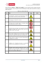
Page 28: ...ential hazards SYMBOL HAZARDS INVOLVED Hot surfaces on the external surface of Moto reducer Danger of moving parts and drive components Do not operate on moving elements Do not tamper or remove the pr...

Page 29: ...ipments Do not use water jets Ban on carrying out operations with live supply voltage for works in progress Do not go up or down the top side of Shredder inside the Segregated zone Feeding Hopper Dang...

Page 30: ...f ambient temperature read the indicates MAX and MIN do not touch the machinery surfaces without protection gloves Burnings could be caused by this operation 2 7 2 Installation site Before the machine...

Page 31: ...r and on the switchboard As regards the lighting modes the user is responsible for the prescriptions stated by the regulations in force and the EEC Directives 2 7 4 Personnel in charge Unloading and m...

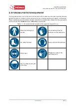
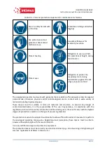
Page 32: ...ces organic or otherwise These substances can be harmful by contact inhalation or contamination Always use the appropriate means of protection Table 2 5 and or Table 2 6 as appropriate Table 2 5 Perso...

Page 33: ...microbiological due to contact with a wide variety of materials including liquids and gases These means must be suitable in terms of materials and structure to prevent any danger of contact contamina...

Page 34: ...dvised to use adequate personal protection equipment ATTENTION The clothing of the person who uses or maintains the machine must meet the essential safety requirements in force in their country as ind...

Page 35: ...INDUSTRIAL SHREDDER Instruction manual for use and maintenance MSM0005EN_F 35 90 This page is left intentionally blank...

Page 36: ...l processed The material is fed through a hopper placed above the shredding chamber The shafts are driven by the electric motor through a reduction stage gear reducer and or a straight tooth gear redu...

Page 37: ...ng hopper which conveys it to the shredding chamber The two blade holding shafts while rotating take the material towards the centre the blades catch onto the material with the beaks placed on their c...

Page 38: ...afts is actuated only after the shredder has been subject to overcharge therefore should any hard material be fed into the shredder such as tempered steel pieces or similar the reversal cannot guarant...

Page 39: ...the drawing 1 Feeding hopper with loading drawer 2 Shredding chamber 3 Electric motor 3 Kw 4 Supporting stand 5 Switchboard and control panel 6 Planetary gearbox with grid protection grid is optional...

Page 40: ...he machine is stable and prevent it from overturning even in the case of accidental impact The holes for anchoring the shredding chamber are provided on the upper part of the stand 3 4 2 Feeding Hoppe...

Page 41: ...MSM0005EN_F 41 90 3 4 3 Shredding chamber It is a cast box consisting of the components as follows A Reduction unit B Frames C Front flange D Blade holding shaft E Blades F Spacers G Cleaning sectors...

Page 42: ...use and maintenance MSM0005EN_F 42 90 3 4 4 Motor drive The shredder is driven by an electric motor which is coupled to the gear reduction unit 1 Electric motor 3 kW 2 Fixing bolts 3 Gearmotor Figure...

Page 43: ...lectric motor a forward running contactor a reverse running contactor The contactors are activated by a P C board which checks the motor absorption through a current transformer and their size suits t...

Page 44: ...24 Electric switchboard with control panel UL compliance 220 V 2 34 120 liter bins 9 3 5 2 Dimensions table Table 3 2 Dimensions cm Typical Shredding chamber 98x39x74 Supporting stand 76x76x107 Feedi...

Page 45: ...ce MSM0005EN_F 45 90 3 6 DECLARATION OF THE SOUND EMISSION VALUES The sound emission is considered with the shredder works without load in maximum nominal speed Table 3 3 Level of average acoustic pre...

Page 46: ...npacked 2 In a normal crate internally lined with tarred paper and blocked on a pallet for transport by sea 3 In a crate internally lined with polythene sheets for road transport in Europe 4 In contai...

Page 47: ...away while the machine is being lowered Failure in complying with these instructions could cause serious injuries When the packages arrive they must be unloaded handled and installed by the Customer...

Page 48: ...o protect the mains to the electric switchboard by means of fuses suitable to feed three phase electric motors rated as reported in the electric component list enclosed in the present manual DANGER To...

Page 49: ...Instruction manual for use and maintenance MSM0005EN_F 49 90 4 1 5 Storage Should the machine not be used after delivery it should be stored in a dry place away from possible impacts and covered with...

Page 50: ...ng to the indications from paragraph 4 1 2 Unloading and handling operations Please refer to the enclosed drawing for details The HDD GLADIATOR series unlike other series of shredders is supplied alre...

Page 51: ...use and maintenance MSM0005EN_F 51 90 4 2 1 Table of lifting chain Table 4 1 Assembly of the Shredder Lifting Chain SHREDDER MODEL CHAIN REFERENCE CHAIN LENGTH CHAIN MIN LOAD REFER TO HDD GLADIATOR L...

Page 52: ...IAL SHREDDER Instruction manual for use and maintenance MSM0005EN_F 52 90 4 2 2 Lifting of the shredding chamber for series HDD GLADIATOR Figure 4 2 How to lift the shredding chamber for series HDD GL...

Page 53: ...g chamber with supporting frame feeding hopper and control panel that can be used as a guideline to set the machine in operation The standard checklist MANUFACTURING AND CONTROL PLAN related to the as...

Page 54: ...cable with the section indicated in the relevant table in the Electrical Equipment list The feeding cable three phase PE is connected according to the regulations in force in the user s Country to th...

Page 55: ...INDUSTRIAL SHREDDER Instruction manual for use and maintenance MSM0005EN_F 55 90 4 5 CONNECTION TO THE COMPRESSED AIR CIRCUIT Unnecessary...

Page 56: ...ng chamber are perfectly tightened WARNING Before starting the shredder always check if the bolts that secure and close the rotating screen to the shredding body are properly tighten 5 1 2 Motor Check...

Page 57: ...mber of turns which pass through the magnetic core The correct number of turns for the motor power is in relation between the voltage nominal current and frequency Refer to MANUFACTURER AND MACHINE ID...

Page 58: ...reached Check the presence of oils and grease and if necessary fill the epicycle and the gear reduction units with oil and the rear bearings with grease Table 5 1 Oil filling Type MANUFAC OIL TYPE GR...

Page 59: ...ual for use and maintenance MSM0005EN_F 59 90 5 1 6 1 Oils zones HDD GLADIATOR series A Oils filling plug B Oil Level indicators C Oil Draining taps D Grease filling plug Figure 5 1 Oil grease lubrica...

Page 60: ...ENCY push button Push the RESET button the yellow signal lamp will start blinking This means that the machine is ready to run and therefore the utmost care must be taken Turn the selector switch FORWA...

Page 61: ...any guarantee on the machine All the machine working stages are controlled by a PC board as shown in the figure The machine overload signal is given by a saturable current transformer whose primary w...

Page 62: ...ing installation is done at Customer charge it will be necessary to execute the electrical tests on the machine as per the EN 60204 The customer test results must be send to intimus International GmbH...

Page 63: ...INDUSTRIAL SHREDDER Instruction manual for use and maintenance MSM0005EN_F 63 90 This page is left intentionally blank...

Page 64: ...to run it after having seen it or having been instructed on the modality of use of the machine The operator MUST NEVER INTERVENE on the machine for inspection or maintenance operations which are the c...

Page 65: ...BLINKER Yellow Lamp It signals that the shredder is ready for starting 3 MAIN SWITCH It disconnects the power line inside the switchboard The connecting conductors from the inlet clamps to the disconn...

Page 66: ...or switch hold to run the blades run in reverse direction and as soon as the selector switch is released the shredder stops 7 STOP BLADES Black push button It stops the motor rotation blades rotation...

Page 67: ...y to interrupt the work and more in detail if you envisage that the machine may remain unguarded always disconnect the main switch IMPORTANT NOTICE Do not start the shafts when the hopper is filled wi...

Page 68: ...vents the machine from restarting and allows the operator to work in safety conditions After having closed the doors again push the RESET button restart the shredder by turning the selector switch FOR...

Page 69: ...the shredder for a new start check that the material collection vessel is empty For the series with the gates check that the doors are closed so that the safety micro switches allow the machine to be...

Page 70: ...hrough a clean contact which closes to ground terminal 3 or 4 it is possible to start or stop the machine This control is used when the machine is connected and operates in line with other machines th...

Page 71: ...der and disconnect the main switch open the switchboard wait till the relay cools down approx 5 min reset the relay by pressing the relevant reset button close the switchboard push the RESET button an...

Page 72: ...t is necessary to run the machine and feeding it with inert material which passing through the blades removes the residues of the previous working cycle Rags paper and sawdust possibly soaked in lubri...

Page 73: ...use and maintenance MSM0005EN_F 73 90 Take out the bolts from the stand and remove it 6 6 4 Reallocation and installation Follow the instructions given in chapters Chapter 4 INSTRUCTIONS FOR INSTALLA...

Page 74: ...dinary interventions depend essentially on the work conditions and therefore on the grade of wear the shredder suffers 7 1 TOOL SUPPLIED FOR INTERVENTIONS ON THE BLADES 7 1 1 Tools supplied table For...

Page 75: ...can be supplied either with or without oils depending on transport distances and specific agreement with the customer The quantities reported in the table are indicative proceed always filling until t...

Page 76: ...opper lift it away from the shredding chamber and place it on the ground Carry out the following checks Check there are no spaces between the blades and spacers to be seen Check that the blades do not...

Page 77: ...the second group of bearings The operator must however pay extreme attention because the sector could free itself and fall during the operation CAUTION The operator must use protective gloves while ta...

Page 78: ...Reassemble the left shaft bearing then the right Reassemble the threaded ring on fast shaft and tighten it to 60daNm Then set the threaded ring on slow shaft and tighten it to 60daNm taking care of ga...

Page 79: ...rt the shredder and make it run in no load conditions for a few minutes checking no interference among the blades nor seizures and clearances are present switch off the shredder and disconnect it from...

Page 80: ...d always filling until the level sign or plug is reached For the Oil refer to paragraph 5 1 6 Empty out the oil contained in the epicycle and gear reduction units and in the bearings housing completel...

Page 81: ...igure 7 1 Figure 7 1 Greasing point electric motors Table 7 2 Grease for electric motors bearings for operating temperatures up to 70 C FRAME SIZE SHREDDER SERIES WORKING HOURS QUANTITY OF GREASE PER...

Page 82: ...s way it will be possible to reach the shredding chamber only after having removed the screws blocking it The opening sequence follows 1 Remove the 6 M8 screws blocking the hopper 2 Tilt the cover hop...

Page 83: ...on the gate Each time the gate is opened to replace the material collection container make sure that the machine stops automatically EVERY 200 HOURS in any case once a month Check the operation of all...

Page 84: ...EN_F 84 90 Table 7 3 Position of the safety devices Typical Device Example image Emergency mushroom button on the control board of the electrical panel Safety microswitch for the mesh hatches of the s...

Page 85: ...ounded and worn A is the original thickness if the difference between A and B is greater than 5mm you must re sharpen To this purpose please contact our Technical Service department IMPORTANT NOTICE I...

Page 86: ...ithout creating further risks due to the environment Proceed as follows disconnect the machine from the electricity supply mains disconnect the electric cables coming out of the disconnect switch disc...

Page 87: ...INDUSTRIAL SHREDDER Instruction manual for use and maintenance MSM0005EN_F 87 90 This page is left intentionally blank...

Page 88: ...two phases in the motor connection Wrong move on direction selector switch Turn the selector switch to forward running 3 THE MACHINE IS JAMMED BY AN OVERLOAD BUT IT DOES NOT REVERSE CAUSE REMEDY Wrong...

Page 89: ...INDUSTRIAL SHREDDER Instruction manual for use and maintenance MSM0005EN_F 89 90 This page is left intentionally blank...

Page 90: ...ATTACHMENT Code Description 190035DC Declaration of Incorporation I68 0033 Blades schema S68 0035 Shredding chamber drawing S68 0036 General drawing 19032PQ0 Manufacturing and Control Plan SE68 0004 0...

Reviews: