INDUSTRIAL SHREDDER
Instruction manual for use and maintenance
MSM0005EN_
F
22 / 90
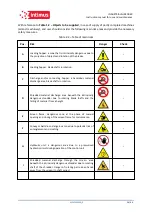
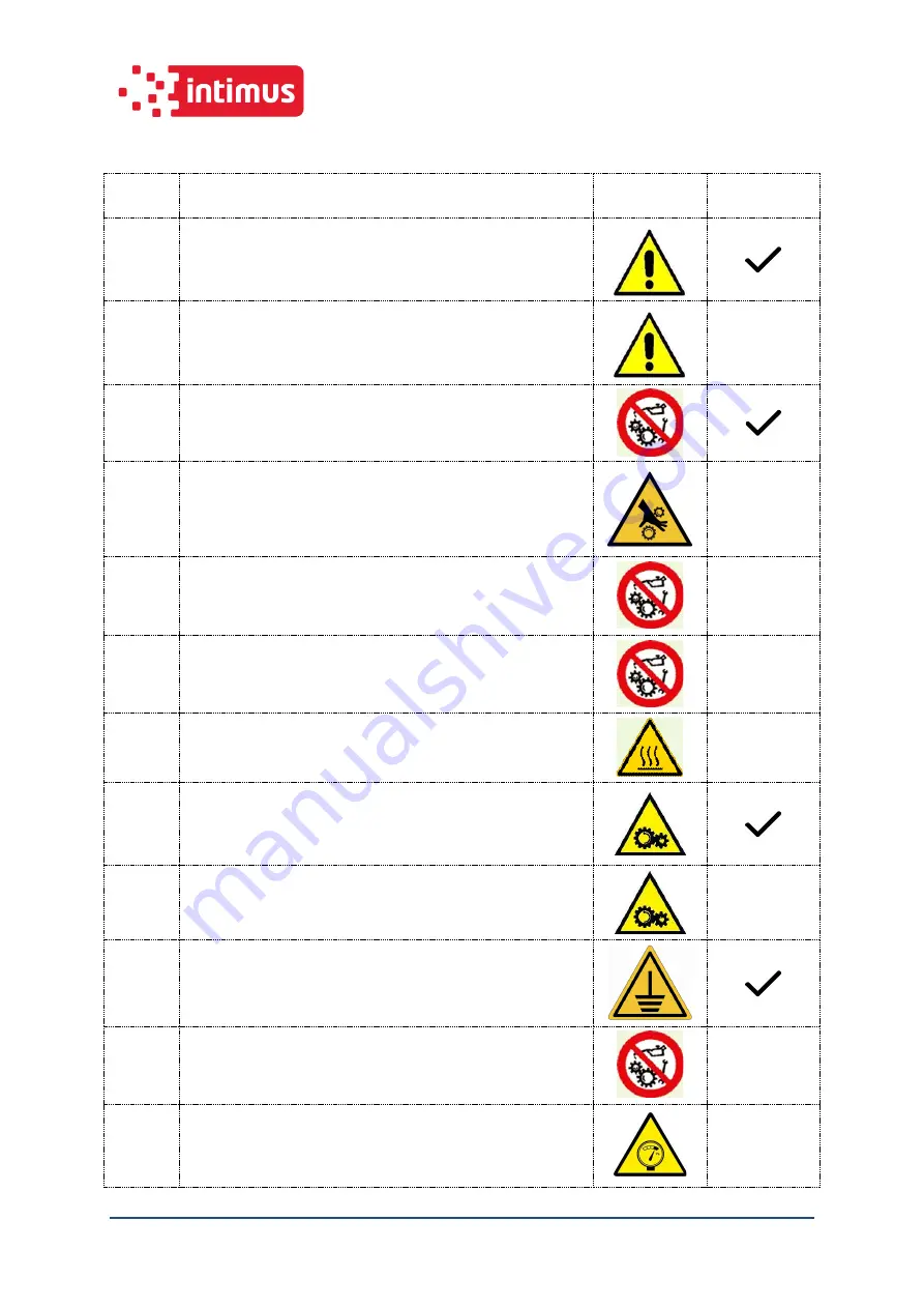
Table 2-1- Table of risks, dangers and protection measures present
Pos.
Description and protection from risks
Danger
Check
1
Feeding hopper with loading drawer: conveys the material to
the shredding chamber and prevents access to an intrinsically
dangerous area in compliance with safety distances.
2
Load hopper cover with PVC sheeting: this prevents the
projection of the material outwards during the shredding
phase.
-
3
Support stand with panels and doors with protective grid: they
prevent the shredded material from being projected and the
dangerous area from being accessed unintentionally.
4
Rotor protection casing: they prevent the access of limbs to an
area with dangerous rotating parts (other series).
-
5
Motor joint protections: they prevent the access of limbs to an
area with rotating parts (other series).
-
6
Motor joint protections (bell): they prevent the access of limbs
to an area with rotating parts (hydraulic control units).
-
7
Grid protection of planetary gearbox: it protects from the
potentially hot surface of the planetary gearbox (optional)
-
8
Key safety micro-switch: it stops operation of the machinery
once the frame doors and the loading hopper inspection door
are opened in order to determine the state of the shredding
chamber (the latter where present).
9
Cable safety micro-switch: it stops operation of the machinery
when the operator is working on the cable (typical use on
conveyor belts).
10
Copper braid: it ensures continuity of the equipotential
protection circuit fixed between the components of the system.
11
Motor belt cover: it protects against fast rotation parts such as
motor pulleys and the corresponding motor drive belts (other
series).
-
12
High pressure hose retaining system (metal cable): it prevents
the violent leaking of the hydraulic oil in operation from the
high pressure pipes on motors and hydraulic pumps, which
causes hose whiplash.
-


