background image


Operation Manual 5280 EPSP 


41 

8. OPERATIONAL ACTIVITIES 

8.1 Replacing the knife in the cutter 

It is recommended, on the basis of experience, to change the knife to sharp after about 8 
hours of effective, continuous work. 


DANGER! 


Do not put hands into the cutting zone! 


  Danger of injury to the operator and auxiliary personnel 

  Danger of injury to hands and hands in the knife area through cutting 

  The edge of the knife is sharp - do not touch 

  Do not handle the knife without the handle 

  The blade may only be changed when the tools for replacing it are undamaged 

  Blunt knives should be put in cassettes immediately 

  Knives intended for scrapping must be deliberately blunted 

  Worn and blunt knives should be sent to the scrap yard 


Summary of Contents for INT-GU-05280EPSP

Page 1: ...280 EPSP Single Knife Paper Cutter Operation Manual intimus International GmbH Bergheimer Stra e 6 12 88677 Markdorf Germany Tel 49 0 7544 60 0 E mail sales de intimus com www intimus com 96256 1 04 2...

Page 2: ...14 2 7 Ways to prevent threats 15 2 8 Safe working rules 16 2 9 Safety control 17 3 TRANSPORT AND STORAGE 18 3 1 Packaging 18 3 1 1 Package characteristic 18 3 1 2 Package removal 18 3 2 Transport 18...

Page 3: ...e of clamping force 39 7 5 4 Rules for selecting the contact pressure 39 7 6 Cutting line indicator optical 39 7 7 Cutting pressing and cutting 39 8 OPERATIONAL ACTIVITIES 41 8 1 Replacing the knife i...

Page 4: ...3 3 Program edit and saving 74 3 4 Cut Save 75 4 CARD CUTTING 76 5 OPTIONS 77 5 1 Options special functions 78 5 2 Options Language 78 5 3 Options Knife change 79 5 4 Options Calibration Base dimensi...

Page 5: ...Operation Manual 5280 EPSP 5 IDENTIFICATION Machine type Single knife paper cutter Item INT GU 05280EPSP...

Page 6: ...Operation Manual 5280 EPSP 6 EC Conformity Declaration...

Page 7: ...be accessible by operator at any time and read carefully by all the machine operators It refers to I Operation and first installation II Troubleshooting of workflow III Maintenance service repairs an...

Page 8: ...n in this manual by the manufacturer 1 3 Documentation This operator manual is deliver with the machine The operator manual is not the service manual It is a must to use only the original spare parts...

Page 9: ...y such This requirement is also applicable to the spare parts used during the repairs The repairs should be made only by servicemen who were trained by the manufacturer In case of the repairs done by...

Page 10: ...age Risk of deterioration of technical condition of machine CAUTION DANGER Danger to life Danger of body damage Dangerous electrical voltage Children must not operate the device Do not put hands under...

Page 11: ...ctical training to familiarize with the content of the document This requirement is especially important for chapter Safety of use The manufacturer recommends that the operator be given the translatio...

Page 12: ...oms Humidity 35 95 non condensed Ambient air temperature 5 C 30 C 2 4 Expected risks when operating the cutter Using the single cutter as intended you can predict some of the risks to your life and he...

Page 13: ...uation of residual risk Intimus International GmbH takes responsibility for the construction of the cutter in order to eliminate the danger although some risk elements during the cutting machine opera...

Page 14: ...your own Prohibition of the cutter in the presence of unauthorized persons especially children No modification of the software of programmable control systems Maintenance and repair of the cutter only...

Page 15: ...re 3 1 Factors and or dangerous places Security measures Identification I MECHANICAL 1 The lever assembly mechanism of the pressure beam drive fixed cover Emergency stop 1 3 4 10 2 Motor belt drive me...

Page 16: ...ecise workpiece machining paint coatings II ELECTRICAL 1 Direct contact of active elements closed housing partially reduced voltage supply to the control system up to 24V AC DC 3 4 2 Indirect touch pr...

Page 17: ...ut in accordance with the law These provisions concern accident prevention guarantee of efficient work and precision of operation eliminating production stoppages Info At the latest after 5 years of u...

Page 18: ...ssories are packed in anti corrosion covers made of plastic and oiled paper 3 1 2 Package removal Used packaging should be removed in accordance with legal regulations applicable in the country of the...

Page 19: ...ters with a pallet truck 3 3 Delivery status The cutter can be supplied by the manufacturer completely assembled and ready for use Fig 6a with disassembled side tables assembly of tables according to...

Page 20: ...re 6b Tightening of the side tables 1 Left side table M8x25 screw 4 pieces washer 8 4 pieces 2 Right side table M8x25 screw 4 pcs 8 washer 4 pcs 3 Left photocell M8x25 screw 4 pcs washer 8 4 pcs M8 nu...

Page 21: ...peration Manual 5280 EPSP 21 Figure 6c Assembling of the base 1 Right side 1 piece 2 Left side 1 piece 3 Bracket 1 item 4 Shelf 1 item 5 Screw M 8x50 8 pcs 6 Screw M 5x16 4 pcs Figure 6d Assembled bas...

Page 22: ...Operation Manual 5280 EPSP 22 Figure 6e Tightening the transport handles Figure 6f Setting the cutter on the base...

Page 23: ...to raise the machine and set it on the base Danger Protect the power cable from sharp tools high temperature and oil 3 4 Setting the cutter Figure 7 Adjusting the cutter setting The slicer does not ne...

Page 24: ...5280 EPSP 24 3 5 Work area In order to easily access the cutter s mechanisms during adjustment maintenance or servicing activities it is recommended to keep a free space of about 0 5 m around the devi...

Page 25: ...g shops and offices 4 2 Basic parameters 4 2 1 Technical data Table 4 PARAMETER 5280EPSP Maximum stack width mm 520 Maximum stack height mm Without false clamp 80 With false clamp 76 Cutting depth mm...

Page 26: ...equency 230 50 Hz Fuse 20A Motor power of the knife drive kW 1 5 Motor power of clamp drive kW 0 37 Motor power of backguage drive kW 0 18 4 2 3 External dimensions The dimensions of cutters in differ...

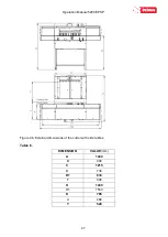
Page 27: ...Operation Manual 5280 EPSP 27 Figure 9b External dimensions of the cutter with side tables Table 6 DIMENSION VALUE mm A 1244 B 904 C 1215 D 730 D1 833 F 400 H 1430 H1 1533 K 785 X 466 Y 520...

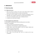
Page 28: ...cutter immediately and block it All defects must be eliminated immediately 5 1 2 Warning about special hazards You should refrain from performing any actions that infringe safety in the machine In par...

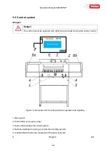
Page 29: ...forming the safety curtain 7 Figure 10 Elements of G 52 cutting machine operation and signaling 1 Main switch 2 Palm button emergency stop 3 Button that activates the control system 4 Buttons enablin...

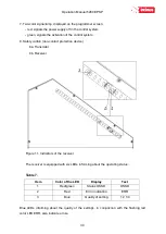
Page 30: ...act protection device 8a Transmiter 8b Receiver Figure 11 Indicators of the receiver The receiver is equipped with six LEDs informing about the operating status Table 7 Item Color of the LED Display T...

Page 31: ...ynchronize with the transmitter It lights up 1 led red The setting is insufficient or the protective field is interrupted at least partially It lights up 2 led red The setting is insufficient or the p...

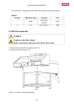
Page 32: ...diode colour Indication Text 1 yellow Work status indicator PWR 2 red Error indication ERR 5 3 Electrical apparatus DANGER Dangerous electrical voltage Before opening the housing switch off the main s...

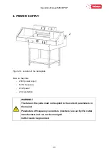
Page 33: ...on the plate 230V power supply 50 Hz frequency 2 kW power 20 A protection WARNING The data on the plate must correspond to the current parameters in the mains Parameters of frequency converters invert...

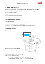
Page 34: ...er 7 2 Danger zones in the cutter knife and clamp zone back side of the cutter frame access to clamp zone and knife back side of the cutter access to the backguage bottom side of the rear table access...

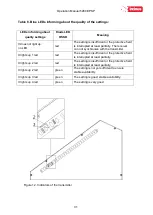
Page 35: ...e quality of the setting using four blue LEDs 3 Fig 11 Table 8 T he setting indicator extinguishes after a suitable time when the safety light curtain is set the LED of the device switching the output...

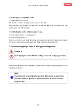
Page 36: ...reen button 2 When the stop has been made during the cutting cycle pressing the cutting buttons again will result in returning to the upper position of the clamping bar and the knife 7 4 Determining t...

Page 37: ...ding the position value on the programmer screen Figure 17 Arrangement of the positioning elements of backguage 7 5 Pressing the material DANGER Do not put your hands into the cutting area when pressi...

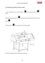
Page 38: ...simultaneously the left cutting button 1 and the pressure button 2 fig 18 2 Release the pressing button 2 pressing will continue for the whole time you hold button 1 3 Release button 1 the clamp will...

Page 39: ...selected experimentally in relation to the type width and height of the cut material The following rules must be observed the higher the pile the greater the downforce the greater the cutting width th...

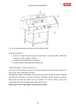
Page 40: ...buttons 3 until the material is cut The return of the knife and its stop in the upper returnable position and the movement of the pressure beam upwards is automatic Releasing the buttons 3 during the...

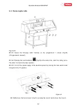
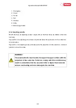
Page 41: ...ne Danger of injury to the operator and auxiliary personnel Danger of injury to hands and hands in the knife area through cutting The edge of the knife is sharp do not touch Do not handle the knife wi...

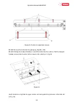
Page 42: ...anual 8 1 1 2 Pressing the push buttons 2 fig 20 at the same time start the cutting cycle The knife 3 is held in the lower position 8 1 1 3 Turn off the power supply of the electrical system by turnin...

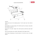
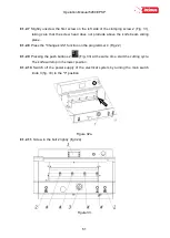
Page 43: ...e power supply of the electrical system by turning the main switch knob 2 fig 22 to position I 8 1 1 6 Turn on the power supply to the control system by pressing the green push button 3 8 1 1 7 On the...

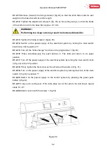
Page 44: ...1 2 Figure 23 8 1 1 9 Unscrew and remove the fastening screws 1 and 2 Fig 23 8 1 1 10 In the place of screws 1 and 2 removed fig 23 screw in the transport handle 1 fig 24 8 1 1 11 Unscrew and remove...

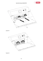
Page 45: ...Operation Manual 5280 EPSP 45 Figure 25 Figure 26...

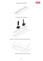
Page 46: ...a time to the left fig 26 and carefully pull the knife down fig 27 Take the removed knife into the special protective packaging Fig 28a 28d With the blade inwards and fasten it with two screws To uns...

Page 47: ...Operation Manual 5280 EPSP 47 Figure 28b Knife in the package Figure 28 c Unscrewing securing the transport handles Figure 28d Fixing the knife in the package...

Page 48: ...oes not protrude below the protrusion 2 in the cutter bar correct position Figure 29 A the adjusting screw protrudes under the projection 2 in the cutter bar incorrect position remove the screw WARNIN...

Page 49: ...kaging Fig 28a 28d 8 1 2 3 Holding the transport handles 1 insert the knife 2 into the cutter so that the transport handles screwed into the knife hit the cutouts in the cutter bar 3 fig 30 Figure 30...

Page 50: ...ach the knife to the cutter bar by turning both transporting handles 1 to the right fig 31 8 1 2 5 Install the fastening screws 2 fig 31 8 1 2 6 Unscrew both transport lugs 1 figure 31 and replace the...

Page 51: ...iding plane 8 1 2 8 Press the Change knife function on the programmer 4 Fig 22 8 1 2 9 Pressing the push buttons 2 Fig 33 at the same time start the cutting cycle The knife will stop in the lower posi...

Page 52: ...rn off the knife change function on the programmer 1 fig 33 8 1 2 16 Press simultaneously the push buttons 2 The knife will return to its upper position 8 1 2 17 Turn off the power supply of the elect...

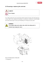
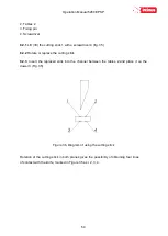
Page 53: ...unting of the knife depend to a large extent on the cutting stick Replacing or reversing the cutting stick is recommended after each knife change or in the event of breaking not cutting the lower shee...

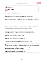
Page 54: ...2 Rotate or replace the cutting stick 8 2 3 Insert the replaced stick into the channel between the tables 2 and place it on the dowel 3 Fig 35 Figure 36 Diagram of using the cutting stick Rotation of...

Page 55: ...events creation of marking made by the lower part of the beam on the material to be cut Figure 37 False clamp plate insert The pressure beam insert fig 37 is attached under the front table in the plac...

Page 56: ...entire surface to the bottom surface of the beam 8 3 5 Use a 3 mm hexagonal wrench to screw in the 4 threaded screws firmly holes in the pressure bar causing the insert to be blocked in the clamping b...

Page 57: ...Operation Manual 5280 EPSP 57 Figure 39 Operating elements used when mounting the insert into the pressure bar...

Page 58: ...removing the cover To adjust backguage 1 unscrew the screws 1 fig 40 2 remove the cover 2 fig 40 3 loosen the screws 1 fig 41 4 loosen the nuts 2 fig 41 5 by turning the screws 3 place the approaching...

Page 59: ...in position 0 9 1 Daily maintenance Every day remove all waste from the cutter and the operator s working space 9 2 Treatments that should be performed cyclically At regular intervals waste and dirt s...

Page 60: ...ng lubrication with a grease apply grease with a grease gun It is enough to press the trigger of the lubricator 2 3 times The indicated points should be lubricated once a week Table 10 List of lubrica...

Page 61: ...Operation Manual 5280 EPSP 61 Figure 42 Way of unscrewing the upper cover 2 and back 1 Figure 43 Method for unscrewing the bottom cover 1...

Page 62: ...Operation Manual 5280 EPSP 62 Figure 44 Lubrication locations of the knife assembly Figure 45 Lubrication points of the knife assembly 1 the pressure beam 2 the guide shaft of the feed mechanism 3...

Page 63: ...e lead screw The worm gear mechanism is filled with an exchangeable oil The exchange should be made after 5 years of work The use of GL 5 and or MIL L 2105D gear oil is recommended 3 3 3 3 3 Figure 47...

Page 64: ...of GL 5 and or MIL L 2105D gear oil is recommended If a lubricant other than the one recommended is used in the reducer the dates of its replacement must be observed The old lubricant must be drained...

Page 65: ...DANGER Risk of injury After lubrication Using a cloth completely remove any excess lubricant grease oil in particular from the table surface on which the cutting material is laid and the work pieces i...

Page 66: ...rs connectors Check the screw connections of the cutter elements and if necessary tighten the screws 9 4 2 Knife regeneration The quality and accuracy of cutting depends primarily on the sharpness of...

Page 67: ...diate loss of the cutter warranty and also releases the manufacturer and the machine supplier from liability for damage caused 10 1 Determining the causes of the fault Determine if the vulnerability a...

Page 68: ...Operation Manual 5280 EPSP 68 PROGRAM MODULE OPERATOR MANUAL...

Page 69: ...n on the screen to start machine control system After pressing Press to calibrate machine starts the calibration During the calibration backgauge moves to the maximum back position then moves forward...

Page 70: ...nput dimension To input the required dimension press the dimension on screen and input value by keyboard Confirm by pressing button ENT and press The backgauge will move to requested position Press he...

Page 71: ...nd next by pressing button Backgauge will automatically move into given position It is possible to repeat the move by pressing Process can be repeated many times 2 3 Manual Backgauge Movement The back...

Page 72: ...program mode 100 programs can be stored in memory including 100 steps dimensions in each program For each step operator can program eject and paper rotation left right 3 1 Program selection Selecting...

Page 73: ...arrows next to the list Delete prog to delete all steps in the program 3 2 Launching program from memory To launch the program please select the requested program and press button PROGRAM START After...

Page 74: ...saving By pressing button Program Edit operator can edit previous selected program Dimension change program name change step removing and turning on off eject After selecting program no i pressing bu...

Page 75: ...delete all steps in the program Delete step to delete one current step 3 4 Cut Save Function allowing to edit program by making backagauge move and cut Pressing Cut Save button activates screen allowi...

Page 76: ...if having a gutter on the sheet if there is no gutter input again card size NOTE Remember to confirm each value but pressing ENT After dimension input and pressing Program Start program starts automat...

Page 77: ...PSP 77 Pressing Program Stop stops card cutting program After each cycle when last stripe is too narrow to cut appears text Pressing YES moves backgauge automatically into first dimension Pressing NO...

Page 78: ...al functions Eject can be set in mm or inches It is value by which paper ream moves forward After cycle backgauge returns to previous position 5 2 Options Language Enter language selection menu Press...

Page 79: ...Operation Manual 5280 EPSP 79 5 3 Options Knife change To enter knife change mode press button Knife change After pressing text on screen appears to confirm Turn on knife change mode...

Page 80: ...ut knife into lower position After knife change please look into guillotine manual for procedure press again button Knife change Text appears Turn off knife change mode By pressing the mode is being c...

Page 81: ...e correction How to make base dimension adjustment move backgauge into position ex 100 0 mm cut paper measure the size if measured size is ex 103 7 mm operator should change dimension by increasing th...

Page 82: ...material cut To change the value use the slider on the touch screen and select values 0 100 0 minimum pressure 100 maximum pressure 5 6 Options Sensor Diagnostics Allows operator to check control sys...

Page 83: ...programs program cancelling This options resets all saved programs 5 8 Options Service to enter service mode Press Service button Keyboard appears on screen to input service code XXXX and press ENTER...

Page 84: ...n program mode with false clamp Min dim 2 min value for guillotine backgauge automatic move in program mode without false clamp Max dim max value for guillotine backgauge automatic move in program mod...

Page 85: ...cancelled by function Factory settings but may need readjustment depending on equipment in the machine Press Yes to return to factory settings 5 8 4 Options Service Calibration Calibration allows to r...

Page 86: ...to dimension speed RH frequency of backgauge speed move speed RL frequency of backgauge speed move on the dimension In table Position first dimension is actual dimension of paper second is dimension c...

Reviews: