background image


Operation Manual 7310 EPSHP 


37 


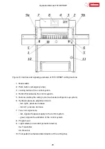
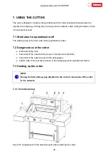
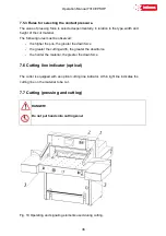
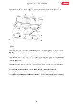
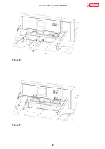
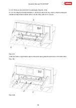
Cutting can be done if: 

1.  there is no object in the work area of the light barrier - the green OSSD 1 LED lights 

up (Fig.11) on the receiver 1 (Fig.19). 

2.  the green push button switch 2 is pressed. 
3.  the two buttons 3 were pressed simultaneously. 

 
Keep both buttons 3 until the material is cut. 
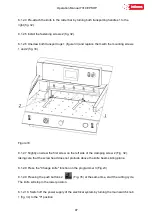
The return of the knife and its stop in the upper return position and the movement of the 
pressure beam upwards is automatic. 
Releasing the buttons 3 during the movement of the pressure beam and the knife downwards 
interrupts this movement. If an object gets caught in the light barrier working area, the 
pressure beam and the knife will stop moving. To continue cutting, remove the unauthorized 
item and simultaneously restart both buttons 3. 

Paper clips or other hard objects can damage the blade! 
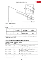
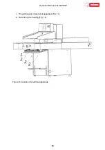
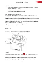
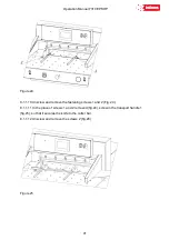
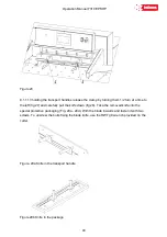
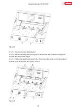
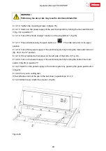
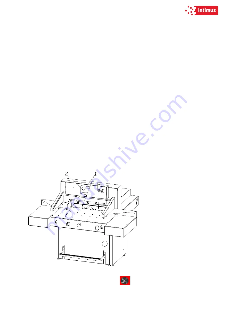
 

7.8 Air Table 

 
The surface of the cutter table is equipped with air nozzles 1 (fig.20. 


Figure 20. 

To turn on the air supply press the blower button 

 on the programmer 2 screen (Figure 

20). 
After switching on the air supply, moving the pile becomes easier. During the cutting, 
pressing or manual pressing (testing), the air supply is switched off automatically 

Summary of Contents for INT-GU-07310EPSHP

Page 1: ...10 EPSHP Single Knife Paper Cutter Operation Manual intimus International GmbH Bergheimer Stra e 6 12 88677 Markdorf Germany Tel 49 0 7544 60 0 E mail sales de intimus com www intimus com 95843 1 04 2...

Page 2: ...8 Safe working rules 15 2 9 Safety control 15 3 TRANSPORT AND STORAGE 16 3 1 Packaging 16 3 2 Transport 16 3 3 Delivery status 18 3 4 Setting the cutter 19 3 5 Work area 20 4 TECHNICAL CHARACTERISTIC...

Page 3: ...67 2 MANUAL MODE 68 2 1 Absolute mode Automatic move to input dimension 68 2 2 Incremental mode Repeating same dimension on next steps 69 2 3 Manual Backgauge Movement 69 2 4 Paper Eject 70 2 5 Numeri...

Page 4: ...Operation Manual 7310 EPSHP 4 IDENTIFICATION Machine type Single knife paper cutter Item INT GU 07310EPSHP...

Page 5: ...Operation Manual 7310 EPSHP 5 EC Conformity Declaration...

Page 6: ...operator at any time and read carefully by all the machine operators It refers to I Operation and first installation II Troubleshooting of workflow III Maintenance service repairs and transportation...

Page 7: ...manual is not the service manual Only use original spare parts The illustrations in the operating instructions may differ from the actual state of the machine The types of auxiliaries indicated in the...

Page 8: ...repairs carried out by unauthorized personnel the warranty granted to the device expires and exempts the manufacturer from any liability for injuries or damage The machine warranty expires if the mach...

Page 9: ...r manufacturer With regard to safety rules in the contents of this instruction by a qualified employee should be understood as a person authorized to set machines circuits and electrical circuits in a...

Page 10: ...2 3 1 Personal protection equipment If necessary or if it results from the regulations in force use the following personal protective equipment Wear safety shoes Wear safety goggles e g when cutting...

Page 11: ...rushing 2 The lever system of the knife drive mechanism Catching crushing 3 The lever system of the knife drive mechanism Crushing 4 The approaching movement of the backguage Crushing 5 Cutting zone C...

Page 12: ...ng the residual risk the cutter is treated as a device that was designed and manufactured according to the state of the art in the year of its manufacture Residual risk assessment When following such...

Page 13: ...Operation Manual 7310 EPSHP 13 2 7 Ways to prevent threats Figure 3 Arrangement of covers and protective elements...

Page 14: ...Machine body Front table Emergency stop 1 3 4 10 11 1 2 8 9 6 Approach move of the knife beam Fixed cover Safety curtain Two handed device Emergency stop 1 7 5 9 7 Approach move of clamp beam Fixed c...

Page 15: ...efore starting work contactless protective device each time before starting work order to carry out maintenance and repairs with disconnected electrical power The above mentioned requirements should b...

Page 16: ...and oiled paper 3 1 2 Removing the packaging Used packaging should be removed in accordance with legal regulations applicable in the country of the user 3 2 Transport The box with the machine should b...

Page 17: ...Operation Manual 7310 EPSHP 17 Figure 5a Transporting the cutter in the crate using a forklift Figure 5b Transporting cutters with a pallet truck...

Page 18: ...y status The cutter is supplied by the manufacturer with the disassembled side tables assembly of the tables according to Figure 6 Fig 6 Tightening of side tables 1 Left side table screw M10x20 4 pcs...

Page 19: ...temperature and oil 3 4 Setting the cutter Figure 7 Adjusting the cutter setting The cutter does not need to be attached to the ground The correct and safe setting of the machine is achieved by turni...

Page 20: ...310 EPSHP 20 3 5 Work area In order to easily access the cutter s mechanisms during adjustment maintenance or servicing activities it is recommended to keep a free space of about 0 5 m around the devi...

Page 21: ...c parameters 4 2 1 Technical data Table 4 PARAMETER 7310 EPSHP Maximum stack width mm 730 Maximum stack height mm Without false clamp With false clamp 100 96 Cutting depth mm 730 Front table lenght mm...

Page 22: ...ncy 3x400 50 V Hz 2x220 60 Control of executive elements VDC 24 Tank capacity l 12 4 2 3 2 Technical data hydraulic oil Table 7 Parameter 7310 EPSHP Oil type HV 46 Quality norm ISO 11158 HV Viscosity...

Page 23: ...4 External dimensions The dimensions of the machine are shown in figure 9 and table 8 Figure 9 Dimensions of the cutter Table 8 Dimension Value mm A 1445 B 924 C 1754 D 1857 E 114 F 658 G 376 H1 1105...

Page 24: ...minated immediately 5 1 2 Warning about special hazards You should refrain from performing any actions that infringe safety in the machine In particular it is prohibited to Putting your hands into the...

Page 25: ...ons enabling the cutting cycle two handed cutting start up system 6 Hydraulic pressure adjustment crank turn right pressure increase turn left pressure decrease 7 Two color signal lamp red signals the...

Page 26: ...Ds informing about quality setting Diode LED OSSD Meaning It does not light up no LED red The setting is insufficient or the protective field is interrupted at least partially The receiver can not syn...

Page 27: ...five core copper wire with 2 5 mm2 wire cross section The user s duty is to install the cutter to the electrical network with 20 A safeguards For connecting use a copper wire with a cross sectional ar...

Page 28: ...Operation Manual 7310 EPSHP 28 1 Hinged housing of electrical apparatus Fig 13 2 Nuts fixing the housing Fig 13 Figure 13 Location of electrical apparatus...

Page 29: ...n the plate 400V power supply 50 60 Hz frequency 3 kW power 20 A protection WARNING The data on the plate must correspond to the current parameters in the mains Parameters of frequency converters inve...

Page 30: ...area is the front side of the operational cutter 7 2 Danger zones in the cutter knife and clamp zone back side of the cutter frame access to clamp zone and knife back side of the cutter access to the...

Page 31: ...ver 4 Fig 15 INFO If after turning on the power supply with the main switch 1 Fig 15 and pressing the green button 2 the LED 3 is green the connection is correct correct direction of rotation if the L...

Page 32: ...r red error LED in combination with blue LEDs indicates the cause of the error DANGER In case of malfunction of photocells immediately contact the service 7 3 3 Emergency stop of the cutter 1 Press th...

Page 33: ...Operation Manual 7310 EPSHP 33 INFO The method of determining the position of the beam as well as the operation of the programmer are described in the Instruction for program unit...

Page 34: ...ial The pressing of the cut material takes place automatically after pressing the buttons that start the cutting cycle 1 fig 18 DANGER Do not put your hands into the cutting area when pressing 7 5 1 M...

Page 35: ...nob 1 reading the pressure value on the pressure gauge 4 Fig 18 turning to the right increasing the pressure turning to the left reducing the clamping force Approximate values of the clamping force de...

Page 36: ...he pile the greater the downforce the greater the cutting width the greater the downforce the harder the material the greater the downforce 7 6 Cutting line indicator optical The cutter is equipped wi...

Page 37: ...vement of the pressure beam and the knife downwards interrupts this movement If an object gets caught in the light barrier working area the pressure beam and the knife will stop moving To continue cut...

Page 38: ...ne Danger of injury to the operator and auxiliary personnel Danger of injury to hands and hands in the knife area through cutting The edge of the knife is sharp do not touch Do not handle the knife wi...

Page 39: ...on the programmer 1 screen Fig 21 Programmer s manual 8 1 1 2 Pressing the push buttons 2 fig 20 at the same time start the cutting cycle The knife 3 is held in the lower position 8 1 1 3 Turn off the...

Page 40: ...f the cutter bar Fig 23 8 1 1 6 Switch on the power supply of the electrical system by turning the main switch knob 2 fig 23 to position I 8 1 1 7 Turn on the power supply to the control system by pre...

Page 41: ...screw and remove the fastening screws 1 and 2 Fig 24 8 1 1 11 In the place of screws 1 and 2 removed fig 24 screw in the transport handle 1 fig 25 so that it secures the knife to the cutter bar 8 1 1...

Page 42: ...Operation Manual 7310 EPSHP 42 Figure 26 Figure 27...

Page 43: ...left fig 27 and carefully pull the knife down fig 28 Take the removed knife into the special protective packaging Fig 29a 29d With the blade inwards and fasten it with two screws To unscrew the bolts...

Page 44: ...Operation Manual 7310 EPSHP 44 Figure 29c Unscrewing securing the transport handles Figure 29d Fixing the knife in the package 1 Packaging 2 Cover 3 Screw 4 Nut 5 Washer 6 Knife 7 Knife change holder...

Page 45: ...r correct position Figure 30 A the adjusting screw protrudes under the projection 2 in the cutter bar incorrect position remove the screw WARNING The assumed knife must be able to support its upper su...

Page 46: ...3 Holding the transport handles 1 insert the knife 2 into the cutter so that the transport handles screwed into the knife hit the cutouts in the cutter bar 3 fig 31 Figure 31 Insert the knife so high...

Page 47: ...e 33 8 1 2 7 Slightly unscrew the first screw on the left side of the clamping screw 2 Fig 32 taking care that the screw head does not protrude above the knife beam sliding plane 8 1 2 8 Press the Cha...

Page 48: ...34 8 1 2 12 Unscrew the fixing screws 4 fig 35 so that the knife falls under its own weight on the base bar with its entire length 8 1 2 13 Tighten the adjustment screws 5 fig 35 as far as they will g...

Page 49: ...o its upper position 8 1 2 18 Turn off the power supply of the electrical system by turning the main switch knob 3 fig 35 to the 0 position 8 1 2 19 Firmly tighten the first screw on the left side of...

Page 50: ...ife depend to a large extent on the cutting stick Replacing or reversing the cutting stick is recommended after each knife change or in the event of breaking not cutting the lower sheets WARNING The c...

Page 51: ...ace it on the dowel 3 Fig 37 Figure 38 Diagram of using the cutting stick Rotation of the cutting stick in both planes gives the possibility of obtaining four lines of contact with the knife marked in...

Page 52: ...in the place shown in figure 40 Figure 40 Placement of the insert before attachment in the pressure bar DANGER Risk of injury In order to mount the insert in the pressure bar 8 3 1 Place the insert 1...

Page 53: ...ping beam 8 3 4 Release the pressure on the pedal 2 Fig 41 the beam with the inserted insert returns to the upper position The removable insert must be attached under the front table Fig 40 INFO The l...

Page 54: ...adjust backguage 8 4 1 unscrew the screws 1 fig 42 8 4 2 remove the cover 2 fig 42 8 4 3 loosen the screws 1 fig 43 8 4 4 loosen the nuts 2 fig 43 8 4 5 by turning the screws 3 place the backguage 4 F...

Page 55: ...Operation Manual 7310 EPSHP 55 Figure 43 Adjusting elements of backguage...

Page 56: ...be put back I nto place immediately after maintenance work has been completed 9 3 Lubrication The list of lubrication points is shown in Figures 46 47 48 49 50 and described in table 12 Access to lubr...

Page 57: ...body Internal surfaces of guides in contact with rollers Side surfaces of the knife body Fixing the hydraulic cylinder of the knife Knife pulley 46a 46b Backguage Oil Guide roller apply a thin layer...

Page 58: ...Operation Manual 7310 EPSHP 58 Figure 45 Base frame covers Figure 46a Space for lubrication of the knife assembly in its upper position...

Page 59: ...Operation Manual 7310 EPSHP 59 Figure 46b Space for lubrication of the knife assembly in its lower position Figure 47 Lubrication space of the pressure beam 3 guide shaft of the backguage mechanism 2...

Page 60: ...Operation Manual 7310 EPSHP 60 Figure 48 Lubricating point of the lead screw Figure 49 Lubrication point of the knife actuator 1 pressure cylinder and shaft actuator 3...

Page 61: ...Operation Manual 7310 EPSHP 61 Figure 50 Lubrication point of the knife assembly lever...

Page 62: ...te ambient temperature of the unit from 5 C to 30 C HV 46 hydraulic oil dust free air free air exchange for cooling the hydraulic oil temperature must not exceed the specified value by the manufacture...

Page 63: ...Using a cloth completely remove any excess lubricant grease oil in particular from the table surface on which the cutting material is laid and the work pieces in contact with the cut material i e the...

Page 64: ...placement of hoses is recommended at least every 6 years 9 5 3 Knife regeneration The quality and accuracy of cutting depends primarily on the sharpness of the knife and the right angle of its blade F...

Page 65: ...er from liability for damage caused 10 1 Determining the causes of the fault Determine if the vulnerability affects the elements electric mechanical hydraulic programmer 10 2 Basic procedures for remo...

Page 66: ...Operation Manual 7310 EPSHP 66 PROGRAM MODULE OPERATOR MANUAL DOP B07S410 7...

Page 67: ...n the screen to start machine control system After pressing Press to calibrate machine starts the calibration During the calibration the backgauge moves to the maximum back position then it moves forw...

Page 68: ...Operation Manual 7310 EPSHP 68 2 MANUAL MODE Available functions 2 1 Absolute mode Automatic move to input dimension Press here to input the value by keyboard Text information...

Page 69: ...move of backguage by same dimension forwards or backwards please input this dimension by pressing it on the screen Use virtual keyboard and confirm by pressing ENT and next by pressing button Backgau...

Page 70: ...e the paper The backgauge automatically move forwards by given value and returns to initial position 2 5 Air Table optional9 Pressing the button turns on off air tables 2 6 Numerical Keyboard Program...

Page 71: ...ht 3 1 Program selection Selecting the program to edit or start Program can be selected from the list which appears on screen after pressing program name Program can be also selected by arrows or inpu...

Page 72: ...dimension saved in step 1 and new screen appears After each cut backgauge moves to next step When last cut is made in selected program backgauge automatically moves to step 1 and program can be repeat...

Page 73: ...program name or change existing name press the window Name Pressing opens keyboard screen which allows to input name After program name confirmation cursor automatically appears on the steps list To...

Page 74: ...ing to edit program by making backagauge move and cut After cut backagauge position is automatically saved as step After next cut automatically changes into next step editing To exit the program edit...

Page 75: ...ng the card cutting sequence Card dimension dimension of stripe Gutter if having a gutter on the sheet if there is no gutter input again card size NOTE Remember to confirm each value by pressing ENT A...

Page 76: ...kgauge to next step without cut Press button to return backgauge to previous step Pressing Program Stop stops card cutting program After each cycle when last stripe is too narrow to cut a text appears...

Page 77: ...anual 7310 EPSHP 77 5 OPTIONS 5 1 Options Special functions Eject can be set in mm or inches It is value by which paper ream moves forward After cycle backgauge returns to previous position Press to c...

Page 78: ...bration without turning off guillotine and optional correction of dimension if display dimension does not correspond to real measured dimension When starting machine operator should measure the paper...

Page 79: ...imension is 680 0 mm change into 683 7mm if measured dimension is 98 4 mm please make correction be decreasing the value difference between screen and real size by 1 6 mm ex if dimension of base is 68...

Page 80: ...Options Reset programs program cancelling This options resets all saved programs 5 6 Options Knife change To enter knife change mode press button Knife change After pressing text on screen appears to...

Page 81: ...put knife into lower position After knife change please look into guillotine manual for procedure press again button Knife change Text appears Turn off knife change mode By pressing the mode is being...

Page 82: ...Options Service 5 7 1 Enter Service mode To enter service mode press Service button Keyboard appears on screen to input service code XXXX and press ENTER NOTE The code is for service information only...

Page 83: ...m max value for guillotine backgauge automatic move in program mode 5 7 3 Options Service Encoder Screw rot mm by lead screw rotation backgauge Encoder type impulses per rotation of encoder 5 7 4 Opti...

Page 84: ...move distance before dimension when backgauge drive is off Move distance where fast backgauge movement is off before reaching position how long backgauge moves slowly into dimension speed RH frequency...

Page 85: ...Operation Manual 7310 EPSHP 85 intimus International GmbH Bergheimer Stra e 6 16 88677 Markdorf Germany Tel 49 0 7544 60 0 E mail sales de intimus com www intimus com 95843 1 04 21...

Reviews: