Operation Manual 7310 EPSHP
40
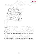
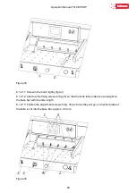
8.1.1.4 Remove the two screws 1 (fig.22) securing the cover 2 and remove the cover 2.
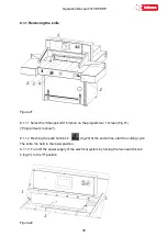
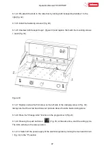
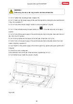
Figure.23
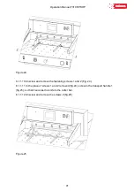
8.1.1.5 Unscrew and remove the first fastening screw 1 from the right side of the cutter bar
(Fig. 23).
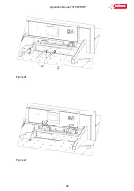
8.1.1.6 Switch on the power supply of the electrical system by turning the main switch knob 2
(fig.23) to position "I"
8.1.1.7 Turn on the power supply to the control system by pressing the green push button 3.
8.1.1.8 On the program screen 4 (fig.23), deactivate the "knife change" function
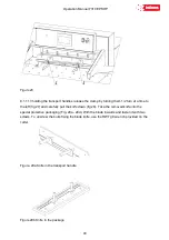
8.1.1.9 Press simultaneously on the push buttons 5. The knife will return to its upper position.
Summary of Contents for INT-GU-07310EPSHP
Page 5: ...Operation Manual 7310 EPSHP 5 EC Conformity Declaration...
Page 42: ...Operation Manual 7310 EPSHP 42 Figure 26 Figure 27...
Page 55: ...Operation Manual 7310 EPSHP 55 Figure 43 Adjusting elements of backguage...
Page 61: ...Operation Manual 7310 EPSHP 61 Figure 50 Lubrication point of the knife assembly lever...
Page 66: ...Operation Manual 7310 EPSHP 66 PROGRAM MODULE OPERATOR MANUAL DOP B07S410 7...

