


Operation Manual 7310 EPSHP
45
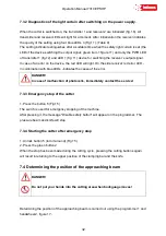
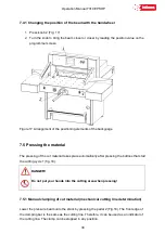
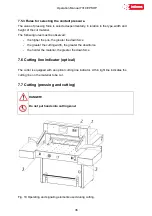
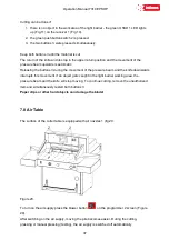
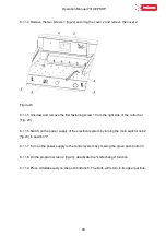
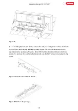
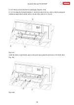
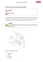
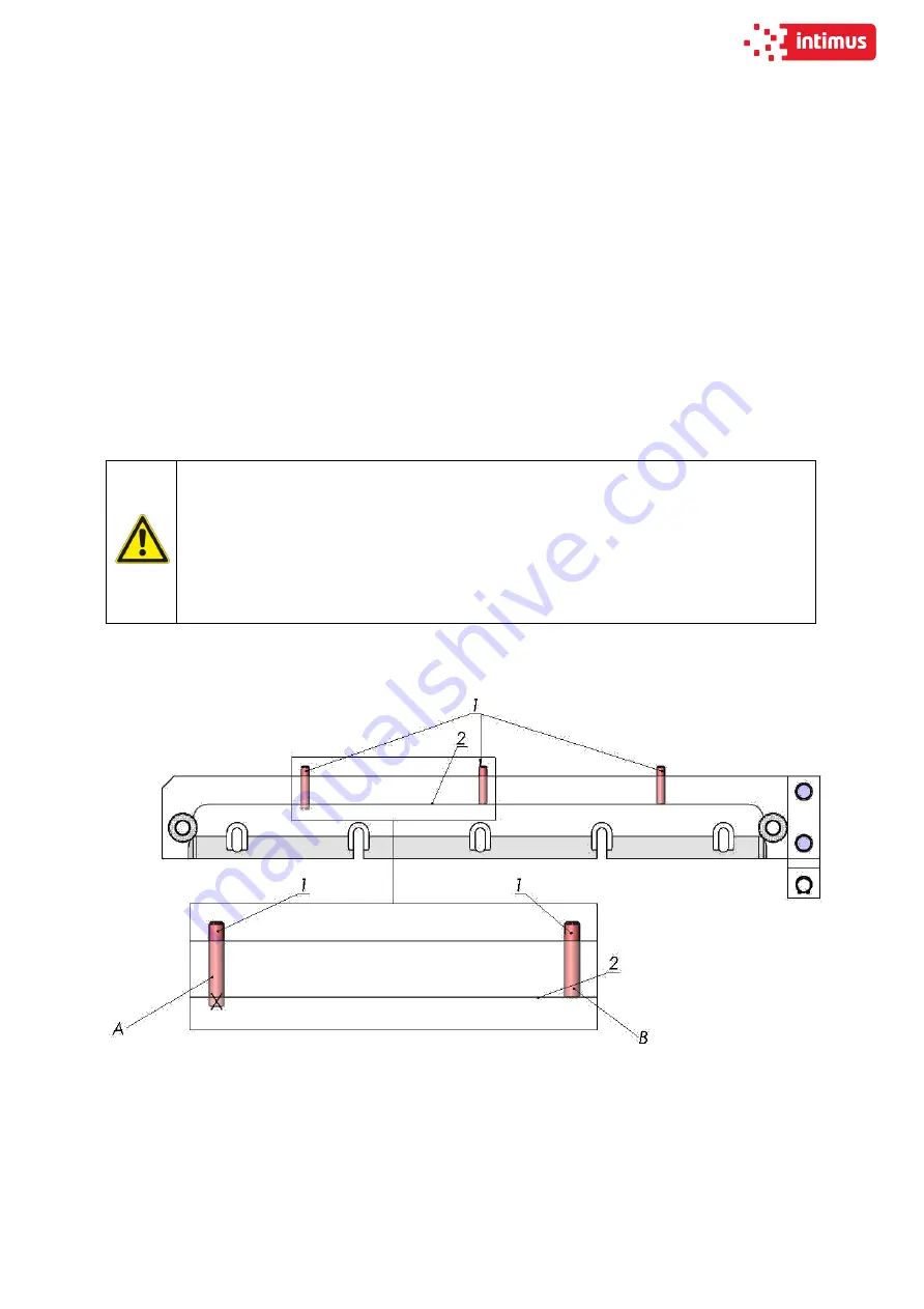
8.1.2 Inserting a knife
8.1.2.1. Remove all adjusting screws 1 (figure 30) so that their faces are hidden in the knife
bar body.
Figure 30 B - the adjusting screw does not protrude below the protrusion 2 in the cutter bar -
correct position.
Figure 30 A - the adjusting screw protrudes under the projection 2 in the cutter bar - incorrect
position, remove the screw.
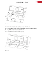
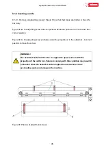
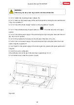
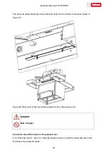
WARNING!
The assumed knife must be able to support its upper surface with the
projection of the cutter bar. Failure to comply with this condition may result in
a situation when the assumed knife is higher than removed, serious
overloading and even damage to the machine.
Figure 30 Position of adjustment screws.
Summary of Contents for INT-GU-07310EPSHP
Page 5: ...Operation Manual 7310 EPSHP 5 EC Conformity Declaration...
Page 42: ...Operation Manual 7310 EPSHP 42 Figure 26 Figure 27...
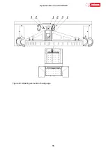
Page 55: ...Operation Manual 7310 EPSHP 55 Figure 43 Adjusting elements of backguage...
Page 61: ...Operation Manual 7310 EPSHP 61 Figure 50 Lubrication point of the knife assembly lever...
Page 66: ...Operation Manual 7310 EPSHP 66 PROGRAM MODULE OPERATOR MANUAL DOP B07S410 7...


