Installation
17
i
BA 14.105/115 EN 2.0
4.2.4
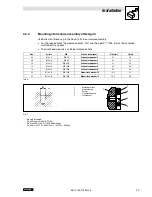
Mounting of armature assembly of design 3
Use bolts with threads up to the head to fix the armature assembly.
•
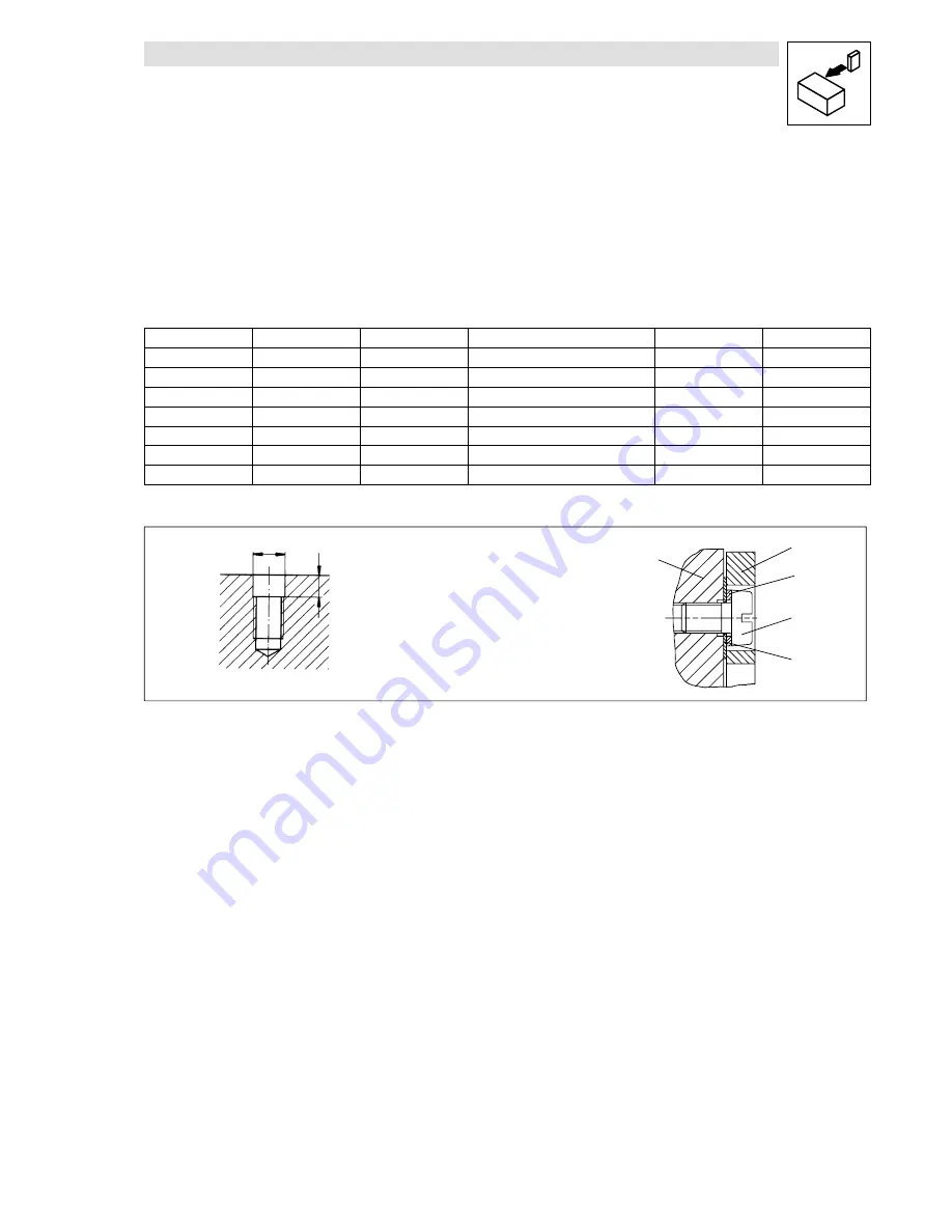
For the tapped holes the clearance bores “Ød” and the depth “t” (Tab. 4) must be observed
maintained in any case.
•
The rivet heads require a sufficient clearance hole.
Size
Screws
DIN
Schnorr lock washer *
Ø
d [mm]
t [mm]
06
M 3 x 8
DIN 84
Schnorr lock washer 3
3.1
0.8
08
M 4 x 10
DIN 84
Schnorr lock washer 4
4.1
1.0
10
M 5 x 12
DIN 6912
Schnorr lock washer 5
5.1
3.5
12
M 6 x 16
DIN 7984
Schnorr lock washer 6
6.1
2.8
16
M 8 x 20
DIN 7984
Schnorr lock washer 8
8.2
3.5
20
M 10 x 25
DIN 7984
Schnorr lock washer 10
10.2
3.5
25
M 12 x 25
DIN 7984
Schnorr lock washer 12
12.2
3.8
Tab. 4
1
2
3
4
5
1
Mounting surface
2
Armature plate
3
Screw
4
Prestressed spring
5
Lock washer
d
t
Fig. 7
*
Source of supply:
Adolf Schnorr GmbH & CO KG
Postfach 60 0162; D-71050 Sindelfingen
Phone: ++49 7031 - 3020; Fax: ++49 7031 - 382600


