background image

Safety information

9

i

BA 14.105/115 EN 2.0

Application range of the INTORQ clutches and brakes

No potentially-explosive or agressive atmosphere.

Humidity, no restrictions.

Ambient temperature -20°C to +40°C

Sparking in switching operation
– Especially at high speeds and high surface speeds of large clutches and brakes sparking

can occur during the switch-on slip phase. This is a completely normal phenomenon of pole
face clutches and brakes. If necessary, insulate the drive system depending on the ambient
conditions.

2.3

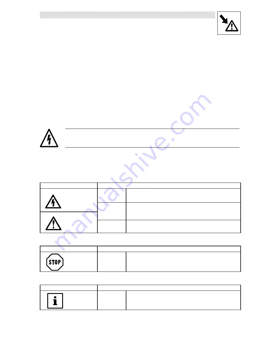
Layout of the safety information

All safety information given in these Operating Instructions have the same layout:

Signal word!

Note

– The icon characterizes the type of danger.
– The signal word characterizes the severity of danger.
– The note text describes the danger and gives information how to prevent dangerous

situations.

Warning of danger to persons

Icons used

Signal words

Warning of hazardous

electrical voltage

Danger!

Warns of

impending danger

.

Consequences if disregarded:

electrical voltage

Consequences if disregarded:

Death or severe injuries.

Warning!

Warns of

potential, very hazardous situations

.

Possible consequences if disregarded:

Death or severe injuries

Warning of a general

danger

Death or severe injuries.

danger

Caution!

Warns of

potential, hazardous situations

.

Possible consequences if disregarded:

Possible consequences if disregarded:

Light or minor injuries.

Warning of damage to material

Icons used

Signal words

Stop!

Warns of

potential damage to material

.

Possible consequences if disregarded:

Damage of the drive system/device or its environment

.

Other notes

Icons used

Signal words

Tip!

Designates a general, useful note.

If you observe it, handling of the drive system/controller will be made easier.

Summary of Contents for 14.105.06 series

Page 1: ...i Operating Instructions BA 14 0175 EN 13056569 Electromagnetic clutch and brake INTORQ 14 105 and INTORQ 14 115...

Page 2: ...NTORQ 14 115 10 INTORQ 14 115 12 INTORQ 14 115 14 INTORQ 14 115 16 INTORQ 14 115 20 INTORQ 14 115 25 What is new what has changed in the Operating Instructions Material number Edition Important Conten...

Page 3: ...Armature design 06 08 10 12 16 1 with outer flange hub 20 25 2 with inner flange hub brakes only 3 without flange hub 5 with flange hub bearing for clutches only Stator design Variants 1 Flange desig...

Page 4: ...f manufacture Nr 00034106 7 5 NM 01 04 05 Packaging sticker Assembly Field Content Example 1 Manufacturer Barcode no D D D D A A A Ae e e er r r rz z z ze e e en n n n j 2 Type see product key Type no...

Page 5: ...afety information 11 3 Data 13 3 1 Product description 13 3 1 1 Flange mounted clutches 13 3 1 2 Shaft mounted clutches 13 3 1 3 Flange mounted brakes 14 3 2 Selection table of clutches 15 3 3 Selecti...

Page 6: ...eadable state 1 1 1 Terminology used Clutches and brakes The terms clutches and brakes will be used for electromagnetic clutches and brakes in the following text Drive system The term drive system wil...

Page 7: ...ctions must not be used at powers higher or lower than indicated in these Instructions Any other use shall be deemed as inappropriate 1 3 3 Legal regulations Liability The information data and notes i...

Page 8: ...safety information These safety notes do not claim to be complete If any questions or problems occur please contact your Lenze representative The clutches and brakes met the state of the technology a...

Page 9: ...cribes the danger and gives information how to prevent dangerous situations Warning of danger to persons Icons used Signal words Warning of hazardous electrical voltage Danger Warns of impending dange...

Page 10: ...is released without residual torque 1 Stator 2 Rotor 5 6 7 Armature assembly sL 1 2 5 6 7 Fig 1 Flange mounted clutch INTORQ 14 105 1 1 3 1 2 Shaft mounted clutches The clutch with magnet frame with b...

Page 11: ...r 1 is centred to the shaft and mounted at the machine panel The armature assembly is connected to the shaft to be braked If a DC voltage is applied the armature plate is attracted against the frictio...

Page 12: ...14 105 25 480 2000 85 75 155 230 70 65x103 555 5 22 5470 5660 4800 3580 7200 Tab 1 3 3 Selection table of brakes Type MK 1 Nm rmax min 1 P20 C W Operating times2 ms QE J QNA kWh Sh h 1 J 10 5 kgm2 Arm...

Page 13: ...reparation 1 Unpack clutch or brake 2 Check completely 3 Check nameplate data especially rated voltage 4 1 1 Product key Type Size Stator design Armature design Armature bore Rotor bore Connection vol...

Page 14: ...RQ 14 105 INTORQ 14 105 INTORQ 14 105 INTORQ 14 105 INTORQ 14 105 INTORQ 14 105 1 1 1 3 1 5 3 1 3 3 3 5 Item 1 2 5 Item 1 2 6 Item 1 2 7 Item 3a 3b 5 Item 3a 3b 6 Item 3a 3b 7 INTORQ 14 115 INTORQ 14...

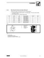
Page 15: ...out x Tab 3 and should not be convex In the case of internal centring the register diameter is machined to an oval clearance When the rotor is assembled dimension b Tab 3 must be observed maintained S...

Page 16: ...a feeler gauge Use shims for the exact air gap setting and for the compensation of wear Stop The armature assembly must be fixed axially 14 105 14 115 Fig 6 Size sL x INTORQ 14 105 INTORQ 14 115 mm mm...

Page 17: ...IN 84 Schnorr lock washer 3 3 1 0 8 08 M 4 x 10 DIN 84 Schnorr lock washer 4 4 1 1 0 10 M 5 x 12 DIN 6912 Schnorr lock washer 5 5 1 3 5 12 M 6 x 16 DIN 7984 Schnorr lock washer 6 6 1 2 8 16 M 8 x 20 D...

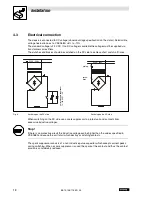
Page 18: ...ary 230V 50Hz 230V 50Hz Universal spark suppressor 14 198 00 01 04 Fig 8 Switching on the DC side Switching on the AC side When switching on the DC side use a spark suppressor to protect coil and cont...

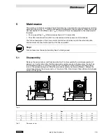
Page 19: ...armature plate Friction marks are thus normal and must not be re worked Stop Friction faces must be kept absolutely free of oil and grease 5 1 Disassembly Remove the axial circlip or shaft locking pla...

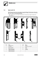
Page 20: ...ced in pairs When ordering spare parts indicate the designation of the parts according to the illustration and list below 3 1 2 10 5 6 7 11 12 11 14 13 15 4 5 10 8 6 Item Name Item Name 1 Clutch stato...

Page 21: ...ch Type Size Spare part Electromagnetic brake Type Size Spare part INTORQ 14 105 10 Item 1 24V 28W INTORQ 14 115 16 Item 6 When you order stators you also have to indicate the coil voltage and power s...

Page 22: ...M hlenstra e 3 4470 ENNS Phone 43 0 7223 886 0 Telefax 43 0 7223 886 997 BELGIUM Lenze b v b a Noorderlaan 133 bus 15 2030 ANTWERPEN Phone 32 0 3 54 26 20 0 Telefax 32 0 3 54 13 75 4 BOSNIA HERZEGOVI...

Page 23: ...elefax 47 64 80 25 11 PHILIPPINES Jupp Company Inc Unit 224 Cityland Pioneer Bldg Pioneer Street MANDALUYONG CITY Phone 63 2 687 7423 683 0042 683 0047 Telefax 63 2 687 7421 POLAND Lenze Rotiw Sp z o...

Page 24: ...INTORQ GmbH Co KG Postfach 1103 D 31849 Aerzen W lmser Weg 5 D 31855 Aerzen Tel 49 0 5154 95 39 01 Fax 49 0 5154 95 39 10 E Mail info intorq de www intorq de...

Reviews: