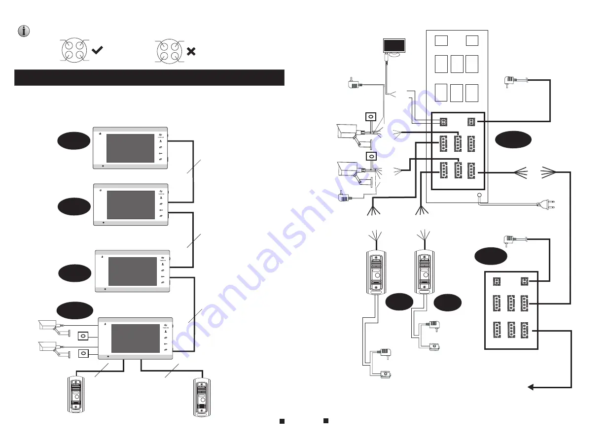
WIRING DIAGRAM
DOOR2
5
6
Note: For the indoor monitor with built-in power supply, the cameras must use
an external power supply.
GND
DC12V
Video
ALM
Power
CAM 1
TV-out
CAM 2
IN
DOOR1
DOOR2
OUT
12V
GND
GND
TV
VIDEO
GND
AUDIO
VCC
VIDEO
GND
AUDIO
VCC
VIDEO
GND
ALM
VCC
VIDEO
GND
ALM
VCC
VIDEO
DATA
GND
AUDIO
VIDEO
DATA
GND
AUDIO
DC-IN
TV-out
CAM 1
IN
DOOR1
CAM 2
DOOR2
OUT
CAM1
D
C
1
2
V
A
u
d
io
G
N
D
V
id
e
o
GND
DC12V
Video
ALM
CAM2
DC-IN
CAM 1
TV-out
CAM 2
IN
DOOR1
DOOR2
OUT
VIDEO
DATA
GND
AUDIO
next
Slave
Master
Slave
AC/DC power
adapter
for unlocking
(not included)
AC/DC
electric lock
(not included)
DOOR2
External switching power supply
(DC 12V)--optional
ALM1
ALM2
D
C
1
2
V
A
u
d
io
G
N
D
V
id
e
o
AC/DC power
adapter
for unlocking
(not included)
AC/DC
electric lock
(not included)
DOOR1
TV
GND
AC/DC power
adapter for
camera
(not included)
AC/DC power
adapter for
camera
(not included)
Built-in power supply
(
AC 100V~240V)
Wiring connection according to the following to avoid interference:
Power+
Video
Audio
GND
GND
Audio
Power+
Video
External switching power supply
(DC 12V)--optional
4
C
4
C
4
C
DOOR
1
DOOR
2
4
C
4
C
CAM1
CAM2
ALAR
M
ALAR
M
Slave
Master
Slave
Slave
Monitorin
g
Unlock
Talk
Hang
up
1
2
Monitorin
g
Unlock
Talk
Hang
up
1
2
Monitorin
g
Unlock
Talk
Hang
up
1
2
Monitorin
g
Unlock
Talk
Hang
up
1
2
MUST ACTIV
AT
E AS 'SLAVE'
MONITOR IN MODE SETTINGS!!!


