Open-Q™ 845 µSOM Development Kit User Guide
Version 1.0
© Copyright Intrinsyc Technologies Corporation
16 of 30
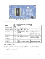
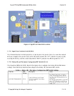
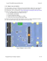
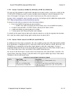
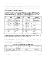
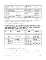
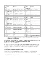
Figure 3. DIP switch assignments
See the table below for a description of the DIP switch connections.
Table 3 - Boot Configuration DIP Switch Settings
Function
DIP
Switch
Description
Notes
FORCED_USB_BOOT
S2600-1
For factory mode programming. Connected
to CPU GPIO57.
For Intrinsyc use only. Leave open /
OFF.
WATCHDOG _DISABLE
S2600-2
Enables WATCHDOG_DISABLE when
DIP switch turned on. Connected to CPU
GPIO101
Unsupported feature. Leave switch open /
OFF.
BOOT_CONFIG[1]
S2600-3
CPU boot configuration bit 1. Connected to
CPU GPIO99
For default boot configuration, leave
open / OFF. Other boot configurations
not supported.
BOOT_CONFIG[2]
S2600-4
CPU boot configuration bit 2. Connected to
CPU GPIO100
For default boot configuration, leave
open / OFF. Other boot configurations
not supported.
CBL_PWR_N
S2600-5
Controls the auto boot of the SOM when
power is applied.
Default configuration is open / OFF. To
enable auto boot of the SOM when power
is applied, set switch closed / ON.
USR_DEBUG 1
S2600-6
User debug switch connected to test point
TP2600.
Default out of the box configuration is
OFF
USR_DEBUG 2
S2600-7
User debug switch connected to test point
TP2601.
Default out of the box configuration is
OFF
USR_DEBUG 3
S2600-8
User debug switch connected to test point
TP2602.
Default out of the box configuration is
OFF
3.7.3
Input Power Selection
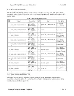
The development kit can be powered using either external DC power supply or by using a battery.
The input power source selection is performed by using the connectors and selection switches shown
in the figure and subsections below.


