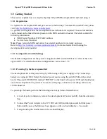
Open-Q™ 845 µSOM Development Kit User Guide
Version 1.0
© Copyright Intrinsyc Technologies Corporation
17 of 30
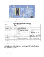
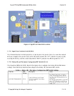
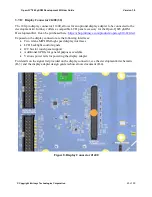
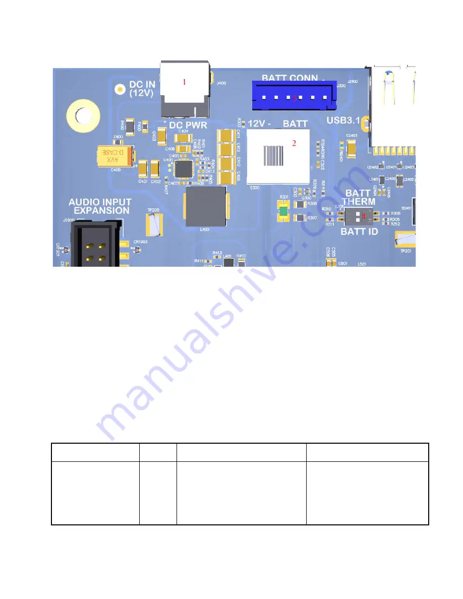
Figure 4. Input Power Selection Locations
3.7.3.1
Input Power Selection Switch S300 (2)
The S300 switch shown in the figure above is used to select the power source. To select the external
DC power supply as the power source, slide the switch towards the ‘12V’ position. To power up the
kit using the battery, slide the switch towards the ‘BATT’ position. The default position is ‘12V’.
3.7.3.2
Battery ID and Thermistor Configuration DIP Switch S301 (4)
The 2-position DIP switch S301 shown in the figure above configures the battery ID and thermistor
settings. The table below describes the settings for the battery ID / thermistor DIP switch.
Table 4 – Battery ID / Thermistor Configuration DIP Switch Settings
Function
DIP
Switch
Description
Notes
BATTERY THERMISTOR
S301-1
Selects whether or not a 10K ohm
thermistor is attached to the battery
connector J300.
For DC powered dev kit, set switch to
closed / ON (default). This enables the
use of the ‘fake’ 10K thermistor on the
carrier board.
For battery powered dev kit, set switch to
open / OFF if thermistor is included on
the battery pack. Otherwise keep switch
closed / ON.


