Open-Q™ 845 µSOM Development Kit User Guide
Version 1.0
© Copyright Intrinsyc Technologies Corporation
21 of 30
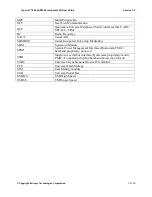
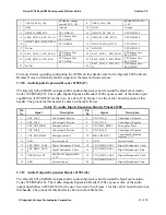
Table 8. Development Kit Buttons (7)
Reference
Designator
User Button
Function
S2500
Use this button to control or increase the volume.
S2502
Volume -/Reset
Use this button to control or decrease the volume. This button can
also be used to reset the board.
S2501
GP Switch
This is a general-purpose user button.
S2503
Power ON
Use this button to power on the Open-Q 845 development kit
(when the auto boot configuration not enabled; see 3.7.2 above).
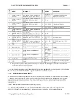
Table 9. Development Kit LEDs (36)
Reference
Designator
LED
Function
DS2500
Blue LED
General purpose LED
DS2501
Green LED
General purpose LED
DS2502
Red LED
General purpose LED
DS2504
Green LED
LED indicates input power
DS2503
Red LED
LED indicates charging state
3.7.8
Debug Serial UART over USB J1600 (12)
The UART connection used on the Open-Q 845 is a USB micro B connector (J1600). This debug
UART is available over USB via the FTDI FT232RQ chip on the carrier board. To get the serial
terminal working with a PC, user needs to ensure that the appropriate FTDI drivers are installed. Use
latest FTDI drivers from
https://www.ftdichip.com/FTDrivers.htm
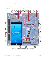
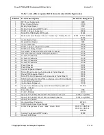
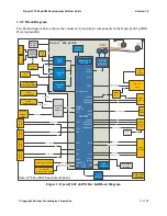
item 12 in Figure 1 for the location of J1600 on the carrier board.
3.7.9
USB 3.1 Type C (for ADB) J2300 (11)
The Open-Q 845 carrier board contains one USB 3.1 Type C connection (J2300). This connection is
used for Android debug bridge (ADB) functionality. To get the adb shell, ensure that the board is up
and running and connect the Type C cable between the board and the PC. Type the command adb
root and adb shell on the PC prompt to exercise the adb shell functionality. While ADB utilizes only
the high-speed channel, this USB type C connector supports the USB 3.1 specification including the
super speed data channel. This USB connection is also uses as the charge source when the dev kit is
powered by a battery and battery charging is enabled (see section 3.7.3 above). See item 11 in Figure
1 for the location of J2300 on the carrier board.
3.7.10
USB 3.1 Type A Connector J2400 (5)
The Open-Q 845 carrier board contains one USB Type A connector J2400 situated on the north side
of carrier board, which exposes USB 3.1 host functionality. This USB connection is designed to
provide up to 1A VBUS current for external devices. See item 5 in Figure 1 for the location of J2400
on the carrier board.
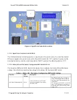
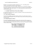
If the user intend to use a mini-PCIe card on the dev kit that requires a USB connection (see 3.7.15
below), then the Mini-PCIe USB enable DIP switch S2401 (6) must be switched to closed / ON
(figure below). If the DIP switch is closed, the USB 3.1 Type A connector is not functional.

