Open-Q™ 845 µSOM Development Kit User Guide
Version 1.0
© Copyright Intrinsyc Technologies Corporation
19 of 30
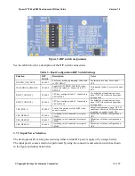
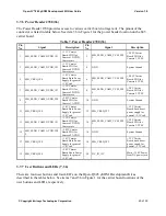
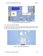
Figure 5. SOM Current Sense Header J301 (5)
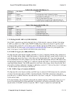
The table below summarizes the pin outs of header J301
Table 6 - Power Header J301 Pinout
Pin No
Signal
Description
1
SOM_PWR_SENSE_P
SOM power positive current sense line
2
SOM_PWR_SENSE_N
SOM power negative current sense line
3
GND
System Ground
To obtain power consumption measurements, the header is connected to a data acquisition unit
(Keithley 2701 or similar) and the voltages on the SOM_PWR_SENSE_P/N pins are captured a few
times a second over the test period (typically 30 minutes). The SOM power consumption is then
calculated as (where Rsense = 5 milliohms):
𝑃𝑃𝑃𝑃𝑃𝑃𝑚𝑚
=
𝑉𝑉𝑃𝑃𝑃𝑃𝑚𝑚
𝑝𝑝𝑝𝑝𝑟𝑟
𝑠𝑠𝑠𝑠𝑠𝑠𝑠𝑠𝑠𝑠𝑁𝑁
∗
(
𝑉𝑉𝑃𝑃𝑃𝑃𝑚𝑚
𝑝𝑝𝑝𝑝𝑟𝑟
𝑠𝑠𝑠𝑠𝑠𝑠𝑠𝑠𝑠𝑠𝑃𝑃
− 𝑉𝑉𝑃𝑃𝑃𝑃𝑚𝑚
𝑝𝑝𝑝𝑝𝑟𝑟
𝑠𝑠𝑠𝑠𝑠𝑠𝑠𝑠𝑠𝑠𝑁𝑁
)
𝑅𝑅𝑃𝑃𝑅𝑅𝑅𝑅𝑃𝑃𝑅𝑅
Use averaging to reduce noise.
3.7.5
Coin Cell Battery Holder B300 (30)
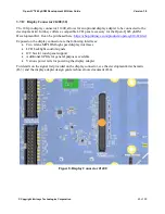
The coin cell holder allows the user to use a coin cell for supplying power to the SOM VCOIN
power input. It is recommended that the Panasonic ML621 series rechargeable coin cell be used (not
supplied with the development kit). See item 30 in Figure 1 for the coin cell battery holder location
on the 845 carrier board.

