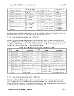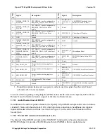
Open-Q™ 845 µSOM Development Kit User Guide
Version 1.0
© Copyright Intrinsyc Technologies Corporation
30 of 30
IEEE802.11 a/b/g/n/ac WLAN standards, and Blu LE 5.x + HS enabling seamless
integration of WLAN/Bluetooth and low energy technology.
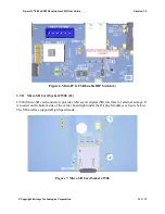
The WCN3990 chipset is located on the µSOM, which has U.FL coax connectors for channel 0
(WLAN+BT) and channel 1 (WLAN only). These connectors are mated to the Carrier board WLAN
/ BT PCB antennas via coax cables. Figure 1 in 3.4.1 above shows how the two WLAN / BT are
routed via the coax cables:
•
For channel 0 (WLAN+BT), see items 31 and 13 on Figure 1.
•
For channel 1 (WLAN only), see items 32 and 14 on Figure 1.
If a more advanced antenna solution is required, it is possible to connect custom antennas directly to
the µSOM U.FL connectors.
3.7.23
Quiet Thermistor RT800 (35)
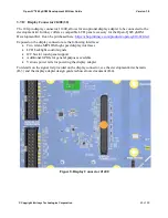
The Open-Q 845 µSOM Development Kit includes a thermistor on the carrier board to allow for
system level thermal management. See item 35 in Figure 1 for the carrier board location of the Quiet
Thermistor RT800.
3.7.24
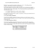
Haptic Output Header J802 (9)
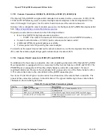
The Open-Q 845 µSOM Development Kit includes a haptic output header J802, giving the user
access to the µSOM PMI8998 PMIC haptic output driver. This driver supports both ERM and LRA
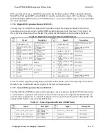
modes. See item 9 in Figure 1 for the carrier board location of this header. The pinout for this header
is shown in the table below.
Table 16. Haptic Output Header Pinout J802
Pin No Signal
Description
1
HAP_OUT_R_P
Haptic output positive
2
HAP_OUT_R_N
Haptic output negative

