12
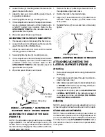
USING CLAMPS
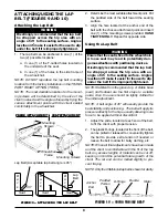
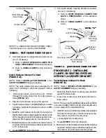
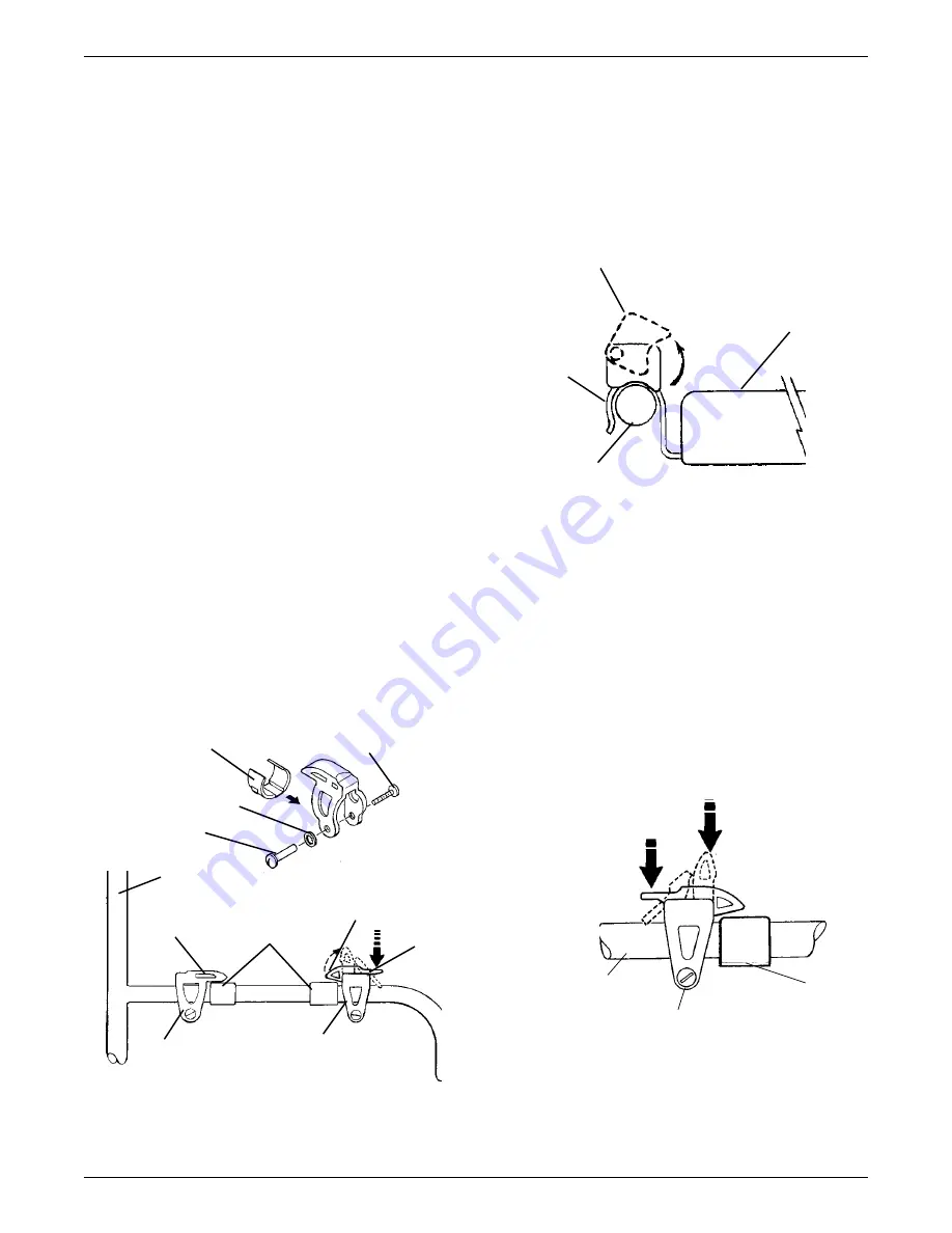
Twist Release (FIGURE 15)
1. To unlock the cane clamp, twist away from the
back cane.
2. To lock the cane clamp, twist in toward the back.
Twist Release
Cane Clamp
Back
Mounting
Hook
Unlock
Back Cane
T
T
T
T
TOP
OP
OP
OP
OP VIEW
VIEW
VIEW
VIEW
VIEW
FIGURE 15 - USING CLAMPS -
FIGURE 15 - USING CLAMPS -
FIGURE 15 - USING CLAMPS -
FIGURE 15 - USING CLAMPS -
FIGURE 15 - USING CLAMPS - TWIST RELEASE
TWIST RELEASE
TWIST RELEASE
TWIST RELEASE
TWIST RELEASE
Fixed Release
Clamp
Fixed
Portion
Quick Release
Clamp
Fixed
Portion
Release
Portion
Mounting
Hooks
FIGURE 14 - QUICK RELEASE
FIGURE 14 - QUICK RELEASE
FIGURE 14 - QUICK RELEASE
FIGURE 14 - QUICK RELEASE
FIGURE 14 - QUICK RELEASE AND FIXED
AND FIXED
AND FIXED
AND FIXED
AND FIXED
RELEASE CLAMPS FOR SEA
RELEASE CLAMPS FOR SEA
RELEASE CLAMPS FOR SEA
RELEASE CLAMPS FOR SEA
RELEASE CLAMPS FOR SEAT
T
T
T
T
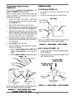
Lock Washer
Sleeve
Internal Mounting Screw
Insert
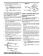
Fixed Release Clamps For Seat
(FIGURE 14)
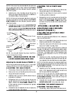
NOTE: Refer to INSTALLATION WARNING in the
SAFETY SUMMARY before proceeding.
NOTE: The quick release and fixed release clamps are
designed to fit either 1-inch rail tubing or, with insert pro-
vided, 7/8-inch rail tubing.
1. Remove the sleeve, lock washer, and internal
threaded mounting screw from the fixed release
clamp (DETAIL “C”).
2. Place the fixed release clamp on the seat rail.
3. If fixed release clamp is not tightly fitted around seat rail
tubing, install insert provided as shown in DETAIL “C”.
4. Install the fixed release clamp onto the back rail so
that the fixed portion is flush against and rests on top
of the mounting hook and is located between the
seat rail and the bottom of the mounting hook.
5. Reinstall the sleeve, lock washer, and internal mount-
ing screw into the fixed release clamp and torque to
75 - inch pounds.
6. Repeat STEPS 1-5 for other side.
7. Once fixed release mounting clamps are secured,
do one (1) of following:
A. Refer to QUICK RELEASE CLAMPS FOR
SEAT in PROCEDURE 2 of this instruction
sheet.
B. Refer to USING CLAMPS in this instruction sheet.
DET
DET
DET
DET
DETAIL
AIL
AIL
AIL
AIL “C”
“C”
“C”
“C”
“C”
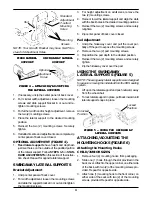
FIGURE 16 - USING CLAMPS - QUICK RELEASE
FIGURE 16 - USING CLAMPS - QUICK RELEASE
FIGURE 16 - USING CLAMPS - QUICK RELEASE
FIGURE 16 - USING CLAMPS - QUICK RELEASE
FIGURE 16 - USING CLAMPS - QUICK RELEASE
Wheelchair
Frame
Mounting
Hook
TO UNLOCK APPLY
PRESSURE HERE
Quick Release
Rail Clamp
TO LOCK APPLY
PRESSURE HERE
Quick Release (FIGURE 16)
1. To unlock, push down on the release tab of the quick
release rail clamps.
2. To lock, push down on the thumb-like feature of the
quick release rail clamps.
Back Cane
NOTE: For TRANSPORT READY OPTION (TRRO)
Twist Release Cane Clamp is REVERSED.
NOTE: For TRANSPORT READY OPTION (TRRO) use
ONLY Quick Release Clamps on Seat Rails.