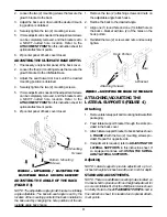
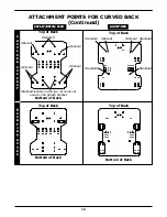
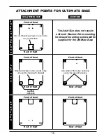
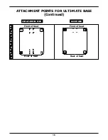
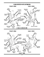
background image

8

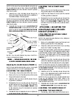
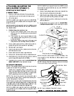
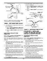
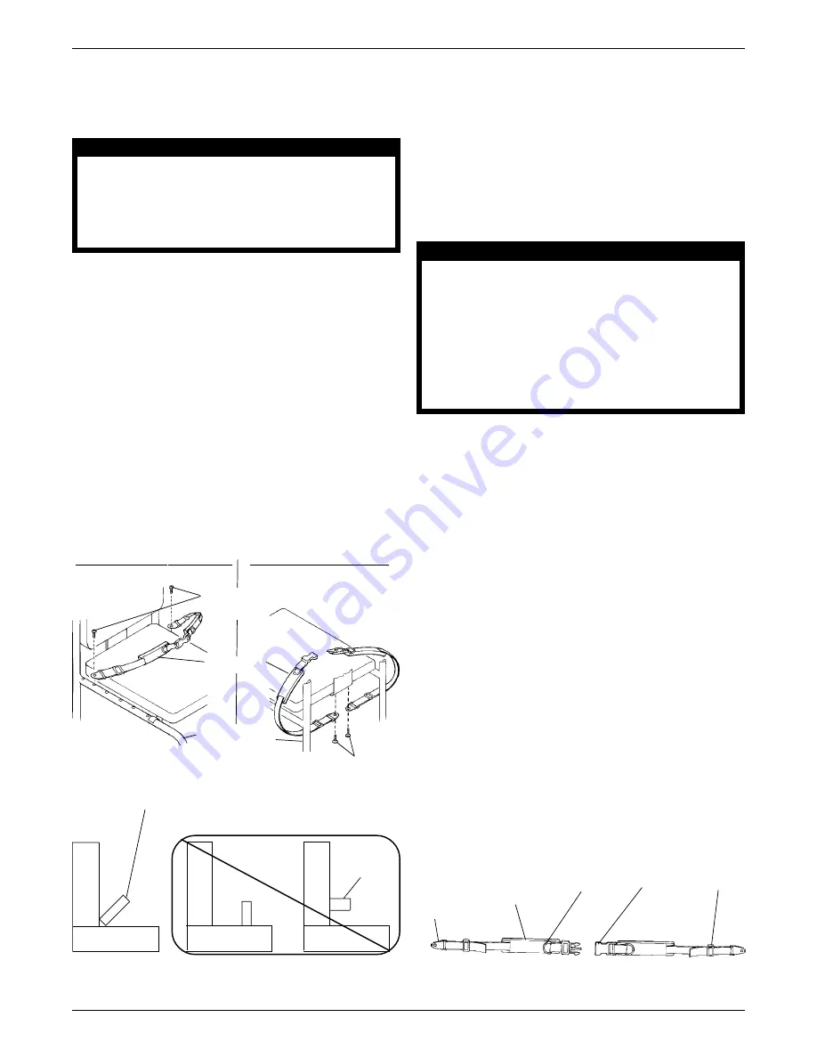
ATTACHING/USING THE LAP
BELT (FIGURES 9 AND 10)

Attaching the Lap Belt

WARNING

It is strongly recommended that the lap belt
be strapped across the hip area with an
angle of 45

 to the seating surface. Angles

less than 45

make it easier for the user to slip

under the belt if it is improperly tightened.

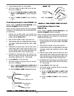
1. The lap belt can be anchored in one (1) of the

two (2) possible locations:

a. In one (1) of the T-nutted holes located on

the underside of the seat.

b. In one (1) of the holes in the side frame of

the wheelchair.

NOTE: DO NOT reposition the lap belt mounting
location from the factory installation on the TRANS-
PORT READY OPTION (TRRO).

NOTE: The most desirable location for the mount-
ing screws will be determined by the size of the
client involved and the angle achieved by trying the
various attachment points with the client seated
comfortably in the wheelchair.
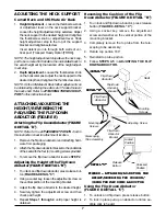
SEA

SEA

SEA

SEA

SEAT


T


T


T


T

 ATT

ATT

ATT

ATT

ATTA

A

A

A

A C H M E N T

C H M E N T

C H M E N T

C H M E N T

C H M E N T

FRAME 

FRAME 

FRAME 

FRAME 

FRAME ATT

ATT

ATT

ATT

ATTA

A

A

A

A C H M E N T

C H M E N T

C H M E N T

C H M E N T

C H M E N T

FIGURE 9 - 

FIGURE 9 - 

FIGURE 9 - 

FIGURE 9 - 

FIGURE 9 - A

A

A

A

A TT

TT

TT

TT

TTA

A

A

A

A CHING 

CHING 

CHING 

CHING 

CHING THE LAP BEL

THE LAP BEL

THE LAP BEL

THE LAP BEL

THE LAP BELT

T

T

T

T

Seat

B
a
c
k

Seat

B
a
c
k

Seat

45

o

Lap
Belt

B
a
c
k

Mounting Screws

Lap Belt

Mounting

Screws

Wheelchair

Frame

Lap Belt (Acceptable lap belt angle is 45

o

)

2. Determine the most suitable attachment point.  Put

the padded side of the belt toward the seating
surface.

3. Align the hole located at the anchor end of the

belt with the chosen attachment point and insert
one (1) of the mounting screws provided. HAND
TIGHTEN ONLY. 
Repeat for opposite side.
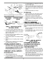
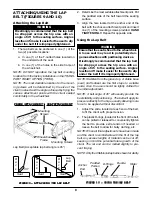
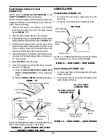
Using the Lap Belt

WARNING

Ensure that the seat is fixed to the wheelchair.
A loose seat may lead to potentially dan-
gerous situations with positioning devices.

It is strongly recommended that the lap belt
be strapped across the hip area with an
angle of 45

 to the seating surface. Angles

less than 45

make it easier for the user to slip

under the belt if it is improperly tightened.

NOTE: Stabilize from the ground up.  A stable base
(seat) and footrest are the first steps to a stable
pelvis. Also, the user should be lightly clothed for
the initial adjustment.

NOTE: A belt angle of 45

o

 will usually provide the

best stability and positioning.  The belt will apply its
pressure directly to the hips, usually allowing more
force to be applied without discomfort.

1. Adjust the slide, located at each end of the belt,

to fit the client with proper tension.

2. The plastic D-rings, located at the front of the belt,

can be pulled or released to conveniently tighten
the belt to provide extra tension if needed or
loosen the belt to allow for bulky clothing, etc.

NOTE: When all final adjustments have been made
and the client is comfortable with the fit of the lap
belt, any excess lengths of material can be cut off,
keeping in mind the potential future growth of the
client. The cut end can be melted slightly to pre-
vent fraying.

NOTE: Only the Child/Junior lap belt is shown for clarity.

D-Rings

Padded

Portion

Slider

Buckle

FIGURE 10 - USING 

FIGURE 10 - USING 

FIGURE 10 - USING 

FIGURE 10 - USING 

FIGURE 10 - USING THE LAP BEL

THE LAP BEL

THE LAP BEL

THE LAP BEL

THE LAP BELT

T

T

T

T

Anchor

End

Summary of Contents for 10R

Page 1: ...the growth bracket provides height adjustment for the Curved Back See FIGURE 1 3 Install four 4 of the mounting screws through the holes in the growth bracket and into the back shell Securely tighten...

Page 2: ...cket and into theundersideoftheUlti matebase Securelytighten NOTE On the Ulti mate base the standard attachment points are the front and rear four 4 holes Refer to the ATTACHMENT POINTS in this instru...

Page 3: ...elateralsupportandmountinghardwarefrom packaging 2 Feed lateral support bracket through the slots pro vided in the back cover 3 Attachlateralsupportbrackettobackshellasshown in FIGURE 2 with the two 2...

Page 4: ...STEPS 3 5 in STAN DARDADJUSTMENTSinthissectionoftheinstruc tion sheet Repeat for opposite lateral support SWINGAWAY LATERAL SUPPORTS Bracket Adjustment 1 Unzip center panel of back cover 2 For width a...

Page 5: ...2 of the mounting screws provided Repeat for opposite side Adjusting the Mounting Hooks NOTE Refer to the ATTACHMENT POINTS chart in this instruction sheet for adjustment locations 1 If necessary unz...

Page 6: ...ure the vertical neck post to the back shell using the two 2 mounting screws provided 5 Close center panel with the vertical neck post ex posed through the slot provided in upholstery 6 Zip the back c...

Page 7: ...Down Abductor Bracket DET DET DET DET DETAIL B AIL B AIL B AIL B AIL B Flip Down Abductor Mounting Screws Telescoping Tube Assembly Flip Down Abductor Bracket Adjusting Screw Using the Flip Down Abduc...

Page 8: ...anchor end of the belt with the chosen attachment point and insert one 1 of the mounting screws provided HAND TIGHTEN ONLY Repeat for opposite side Using the Lap Belt WARNING Ensure that the seat is f...

Page 9: ...hardware is tight at ALL times INSTALLATION WARNING DO NOT install twist quick and fixed release clamps in any other locations than specified in this instruction sheet otherwise the seating sys tem w...

Page 10: ...seat rail tubing install insert provided as shown in DE TAIL A 4 Install the quick release clamp onto the seat rail so that the fixed portion is flush against and rests on top of the mounting hook an...

Page 11: ...E CLAMPS FOR B FIGURE 13 FIXED RELEASE CLAMPS FOR B FIGURE 13 FIXED RELEASE CLAMPS FOR BA A A A ACK CK CK CK CK DET DET DET DET DETA I L A I L A I L A I L A I L B B B B B Lock Washer Sleeve Mounting H...

Page 12: ...release clamp DETAIL C 2 Place the fixed release clamp on the seat rail 3 Iffixedreleaseclampisnottightlyfittedaroundseatrail tubing installinsertprovidedasshowninDETAIL C 4 Install the fixed release...

Page 13: ...E E C C C C C K K K K K S S S S S U U U U U P P P P P P P P P P O O O O O R R R R R T T T T T G G G G G R R R R R O O O O O W W W W W T T T T T H H H H H B B B B B R R R R R A A A A A C C C C C K K K...

Page 14: ...L L D D D D D E E E E E R R R R R S S S S S U U U U U P P P P P P P P P P R R R R R O O O O O T T T T T M M M M M O O O O O U U U U U N N N N N T T T T T I I I I I N N N N N G G G G G H H H H H O O O...

Page 15: ...combination Front of Seat Rear of Seat G G G G G R R R R R O O O O O W W W W W T T T T T H H H H H B B B B B R R R R R A A A A A C C C C C K K K K K E E E E E T T T T T Lap Belt Optional Rear of Seat...

Page 16: ...SIZE CHILD JUNIOR SIZE CHILD JUNIOR SIZE ADUL ADUL ADUL ADUL ADULT S I Z E T S I Z E T S I Z E T S I Z E T S I Z E Front of Seat M M M M M O O O O O U U U U U N N N N N T T T T T I I I I I N N N N N G...

Page 17: ...upport Lap Belt Mounting Hook Neck Support CHILD JUNIOR SIZE Ulti mate Base Curved Back Mounting Hook Curved Back Mounting Hook Ulti mate Base Shoulder Support Lateral Support Neck Support Lap Belt Tr...

Page 18: ...colored NEOPRENE child cushion covers NOTE We recommend cleaning the cover on a regular basis Inner Cover If applicable 1 Hand wash with a damp cloth 2 We DO NOT recommend machine washing or dry ing...

Page 19: ...12 12 12 12 11 11 11 11 11 6 6 6 6 6 12 12 12 12 12 1 0 1 0 1 0 1 0 1 0 5 5 5 5 5 8 8 8 8 8 1 2 1 2 1 2 1 2 1 2 1 1 1 1 1 1 1 1 1 1 12 12 12 12 12 12 12 12 12 12 1 1 1 1 1 2 2 2 2 2 4 4 4 4 4 9 9 9 9...

Page 20: ...sfactory warranty service please write directly to Invacare at the address on the next page Provide dealer s name address model number date of pur chase indicate nature of the defect and if the produc...

Reviews: