background image

Invacare® Homecare Beds

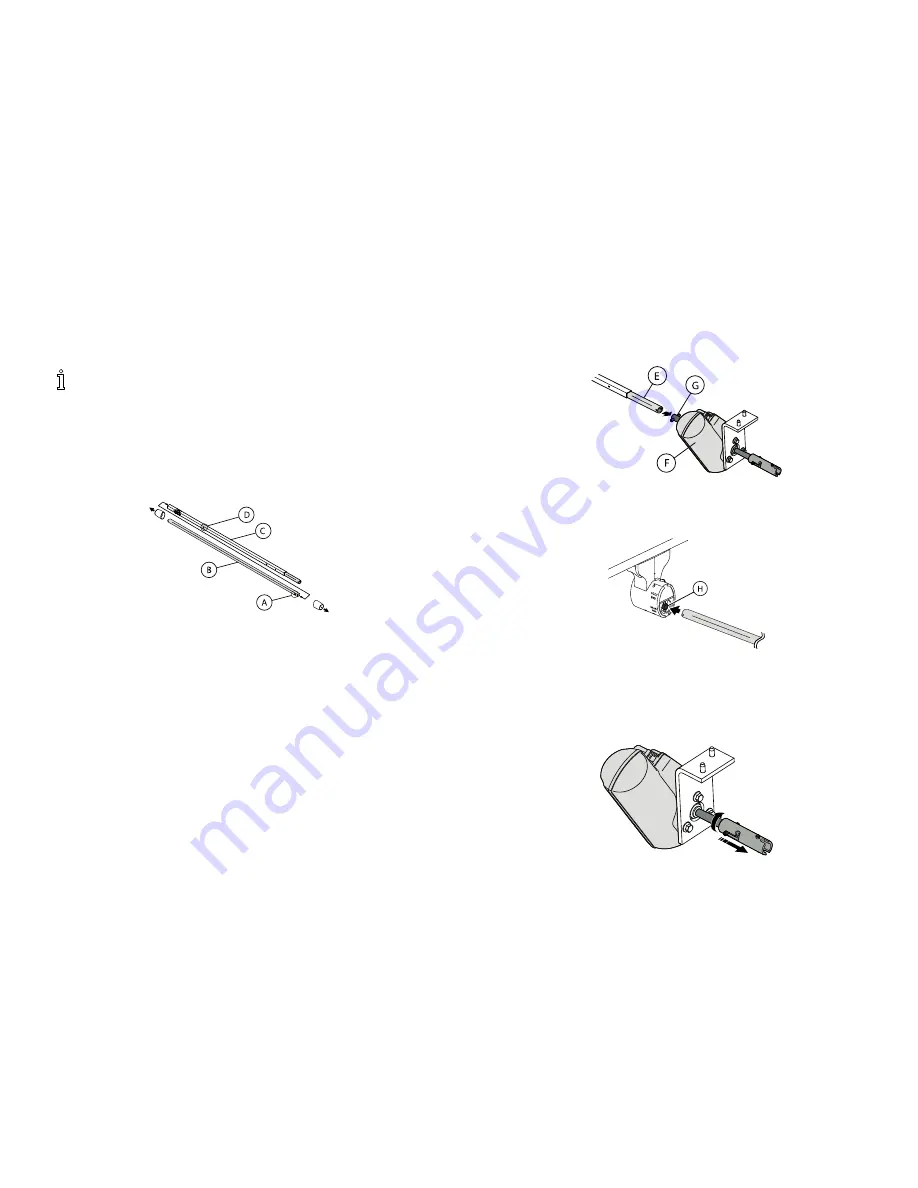
4.10 Assembling/Installing/Removing Drive
Shaft

Reverse this procedure to remove the drive shaft.

The drive shaft for Hi/Lo function consists of two
sections that are shipped unassembled. The inner
drive shaft has a positioning spring button, and
the outer drive shaft has multiple holes and a
spring-loaded end.

1.

Remove the plastic caps from each end of the drive
shaft.

2.

Press the spring button

A

on the inner drive shaft

B

and insert the inner drive shaft into the outer drive
shaft

C

.

3.

Engage the spring button into the third positioning hole

D

.

4.

Push in on the spring loaded end of the drive shaft

E

and attach to the Hi/Lo motor

F

output shaft

G

.

5.

Attach the drive shaft to the gear box head end

H

(bottom opening) at the head end of the bed.

6.

Ensure the Hi/Lo motor output shaft spring-loaded
coupler is properly aligned with the foot end gear box.

26

1114836-H-05

Summary of Contents for 5307IVC

Page 1: ...care Beds 5411IVC 5410IVC 5311IVC 5310IVC 5307IVC 5411LowIVC 5410LowIVC en User Manual This manual MUST be given to the user of the product BEFORE using this product read this manual and save for futu...

Page 2: ...whole or in part is prohibited without prior written permission from Invacare Trademarks are identified by and All trademarks are owned by or licensed to Invacare Corporation or its subsidiaries unles...

Page 3: ...alling Low Bed Ends 25 4 9 1 Installing the Casters onto the Low Bed Ends 25 4 10 Assembling Installing Removing Drive Shaft 26 4 11 Inspecting the Bed 27 4 11 1 Installing Removing Cable Lock 29 4 11...

Page 4: ...ing indicates a potentially hazardous situation which if not avoided could result in death or serious injury CAUTION Caution indicates a potentially hazardous situation which if not avoided may result...

Page 5: ...5 Rinse thoroughly with water maximum temperature 110 6 Dry all components before storing CLEANING INSTRUCTIONS See Owner s Manual P N 1116654 Underside of bed shown Warning Label 1117179 Rev B locate...

Page 6: ...m 2 in BED END 26 in 66 7 cm to 33 in 85 7 cm COMPONENTS Head Spring Universal Bed Ends Foot Spring Two Motors Manual Single Crank Hi Lo 5307IVC SHIPPING WEIGHT 161 5 lbs 73 3 kg WEIGHT CAPACITY OCCUP...

Page 7: ...MATTRESS 5180 20 lbs 9 1 kg 5184 26 lbs 11 8 kg 5185 30 lbs 13 6 kg 5185XL 30 lbs 13 6 kg Accessories are subject to change Contact Dealer or Invacare for current list DESCRIPTION MODEL NUMBER WEIGHT...

Page 8: ...amage and test components before use DO NOT use product if components are damaged or if product is not working properly Contact a qualified technician or Invacare for repair DANGER Risk of Death Injur...

Page 9: ...around the product to dry thoroughly before using the controls again DANGER Risk Of Death Injury Or Damage To avoid shock product damage and personal injury DO NOT use outdoors Connect this product to...

Page 10: ...s properly locked some flooring surfaces such as tile or wood will allow the bed to move under some conditions Using the bed on these types of surfaces MUST be evaluated by the care provider DO NOT tr...

Page 11: ...y size may also have an increased risk of entrapment Monitor patients with these conditions frequently Place the mattress deck in the flat position when left unattended WARNING Risk Of Injury Or Adver...

Page 12: ...and the bed frame ALWAYS test to make sure that the side rails are properly and securely in place before using Otherwise injury or damage may occur DANGER Risk Of Injury Or Adverse Health Consequences...

Page 13: ...iations in bed side rail design width and thickness or firmness of the mattress could cause contribute to entrapment DANGER Risk of Death Injury or Damage To avoid injury or damage from misuse or entr...

Page 14: ...change the plug in any way WARNING Risk Of Injury Or Damage To avoid product damage and personal injury Disconnect pendant when not in use and store out of reach of children Grounding Information WAR...

Page 15: ...GER Risk Of Death Injury Or Damage To avoid bed collapse and resulting injury or damage The weight limit of the occupant of the bed CANNOT exceed 350 lbs 159 kg The TOTAL weight limit of the bed inclu...

Page 16: ...se of mattress keepers DANGER Risk Of Injury Or Adverse Health Consequences Fall hazard exists due to incorrect installation of bed rails To avoid injury ensure that the Invacare bed rails are install...

Page 17: ...double insulated construction Servicing a double insulated product requires extreme care and knowledge of the system and is to be done only by qualified service personnel Replacement parts for a doubl...

Page 18: ...ign the copy acknowledging the count 4 If shortage occurs IMMEDIATELY contact Invacare Customer Service department at 800 333 6900 4 2 Unpacking DANGER Risk of Injury or Damage Continued use of the pr...

Page 19: ...pieces D One Hand Crank E Unpacking Foot and Head Spring Sections A B C D 1 Remove any loose packing A from the carton B 2 Foot Spring Section carton includes One Foot Spring C electric beds include p...

Page 20: ...inches Measurements taken from floor C to bed deck D 4 3 Inspecting DANGER Risk Of Injury Or Damage To avoid injury or damage inspect the following and contact a qualified technician or Invacare if a...

Page 21: ...the left For set up purposes the motors on the semi electric 5890IVC and 5891IVC and full electric 5490IVC and 5491IVC foot springs as well as the crank handles on the manual foot springs 5770IVC shou...

Page 22: ...the head pull tube assembly A from the side frame of the foot spring remove the hitch pin E and grommet washer F from the clevis pin G 2 Extend the inner pull tube shaft C manually until the spring b...

Page 23: ...they will always be assembled diagonally opposite each other when inventory is mixed If two locking casters are not included with the bed contact a qualified dealer 1 To install casters A lay the bed...

Page 24: ...side and raise it until the rivets on the corner plates of the spring section are high enough to place into the corner locks D on the bed end WARNING Risk of Injury or Damage To avoid injury or damage...

Page 25: ...casters only operate when bed is in lowest position Always install locking caster in the same location on each bed end so that they will always be diagonally opposite each other when bed is assembled...

Page 26: ...plastic caps from each end of the drive shaft 2 Press the spring button A on the inner drive shaft B and insert the inner drive shaft into the outer drive shaft C 3 Engage the spring button into the...

Page 27: ...on the product DO NOT unplug the power cord from the junction box Damage to cord will result 4 11 Inspecting the Bed Electric Beds WARNING Risk of Injury or Damage To avoid injury or damage When insta...

Page 28: ...moving Cable Lock page 29 6 If damage is found contact an Invacare Customer Service Representative to report the damaged items and request appropriate replacement parts or products WARNING Risk of Inj...

Page 29: ...lick in place Removing 1 Compress the cable lock clips B firmly 2 Carefully pull the cable lock F away from the junction box D 3 Slide the cable lock F off of the cables E 4 11 2 Installing the Manual...

Page 30: ...cable C 2 Unplug the standard pendant cable from the extension cable 4 12 Storing the Bed WARNING Risk Of Injury Or Damage To avoid product damage and personal injury DO NOT place other objects on to...

Page 31: ...DO NOT place pendant under or between objects WARNING Risk Of Injury Or Damage A safety feature of this product includes protection against overheating caused by excessive or extended periods of opera...

Page 32: ...bed operations A Bed End B Head Section C Foot Section D Locking Caster E Bed Frame F Emergency Crank To operate the Electric bed using the six button controller refer to 5 2 Operating Full Electric...

Page 33: ...emergency crank to allow the bed to be lowered in the event of a power outage Raising and Lowering the Head and Foot Sections G H Link Fabric not shown 1 To raise the head of the bed G press the Head...

Page 34: ...ical connections and mechanical hook ups All semi electric beds come with an emergency crank to allow the bed to be lowered in the event of a power outage Raising and Lowering the Head and Foot Sectio...

Page 35: ...the emergency crank Failure to remove the emergency crank may cause damage or personal injury The emergency crank MUST be removed before the bed is used A B C You should find the emergency crank store...

Page 36: ...sk Notification Guide that accompanies this manual and is included with each bed rail kit The Bed Rail Risk Notification Guide can also be found at www invacare com DANGER Risk Of Death Injury Or Dama...

Page 37: ...roken if excessive side pressure is exerted on the bed rails These bed rails are used for the purpose of preventing an individual from inadvertently rolling out of bed The bed rails are not intended n...

Page 38: ...enance according to the recommended schedule in this manual The effective bed lifetime can vary according to the frequency and intensity of use 6 2 Wear and Tear Items Normal wear and tear items and c...

Page 39: ...njury or Damage To avoid damage to electric controls If a liquid is spilled in or around the electric bed unplug the electric bed before cleaning Clean up the spill and allow the electric bed or the a...

Page 40: ...he bed 4 Tip bed end from side to side to allow any collected or trapped water to drain 5 Thoroughly towel dry bed end and all components 6 Repeat drying process until all components are dry Ensure th...

Page 41: ...eplace if missing or damaged In addition dealers should inspect bed ends for proper operation 1 Adjust bed ends to the lowest position 2 Remove bed ends from head or foot spring 3 Remove bed end caps...

Page 42: ...the preceding inspection criteria and the bed is ready for placement into a client s home q FAIL Bed or any component has failed any of the preceding inspection criteria Tag the bed or component with...

Page 43: ...o not move Manual Beds crank s not working Call dealer Bed ends move in opposite directions electrical or manual bed Drive Shaft connected to wrong gear box shaft Call dealer Crank not properly instal...

Page 44: ...not stop moving Pendant Check for depressed stuck buttons If button is stuck call dealer for repair Bed Hi Lo movement does not stop Cables Check cables if damaged call dealer Bed is producing unusua...

Page 45: ...es are not entangled pinched Call the dealer for repair replacement of cables and or motors Broken cable lock Call dealer to replace cable lock Household fuse or breaker blown Check household fuse bre...

Page 46: ...care product In the event you do not receive satisfactory warranty service please write directly to Invacare at the address on the back cover provide dealer s name address and the date of purchase ind...

Page 47: ...Notes...

Page 48: ...Elyria Ohio USA 44035 800 333 6900 Canada 570 Matheson Blvd E Unit 8 Mississauga Ontario L4Z 4G4 Canada 800 668 5324 Manufacturing Location 2101 E Lake Mary Blvd Sanford Florida USA 32773 1114836 H 05...

Reviews: