SECTION 4—PACKAGING, HANDLING, AND SET-UP
Part No 1114836
31
IVC
™
Bed Series
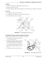
Installing
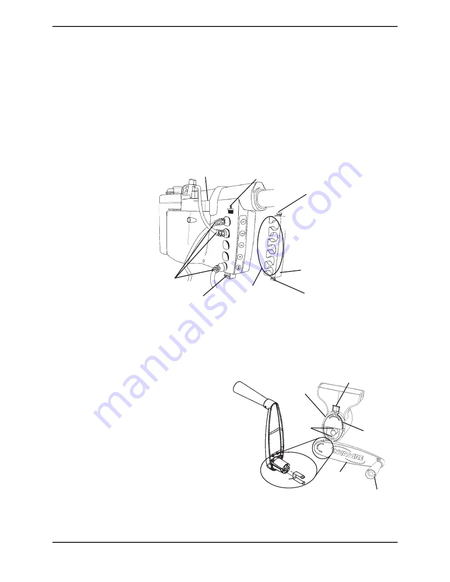
1. Slide the cables into the appropriate cable lock slots.
2. Depress the cable lock clips.
3. Push the cable lock clips into the locking slots on the junction box, until they click in place.
Removing
1. Compress the cable lock clips firmly.
2. Carefully pull the cable lock away from the junction box.
3. Slide the cable lock off of the cables.
FIGURE 4.12
Installing/Removing Cable Lock
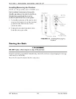
Installing the Manual Crank for Hi/Lo Function
NOTE: For this procedure, refer to FIGURE 4.13 on page 31.
1. Pinch the ears on the input drive shaft
cover to open the cover.
2. Flip the input drive shaft cover up and
push until it attaches to the gear box.
The cross pins will now be accessible.
3. Connect the manual crank to the cross
pins until the spring engages the cross
pins.
4. Unfold the handle on the hand crank.
FIGURE 4.13
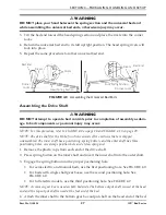
Assembling the Drive Shaft
Cable Lock
Slots
Cable
Lock Clip
Cable
Lock Clip
Cable
Lock
Cables
Locking Slot
Locking Slot
Junction Box
Input Drive
Shaft
Cover
Gear Box
Crank
Spring
Ears
Handle
Cross
Pins


