20
21
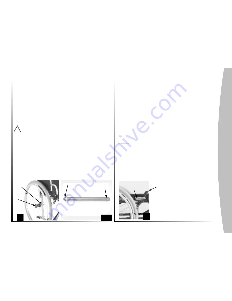
2.3.3 Axles (photo 10)
The Quick release axles connect the wheels and frame :
Depress the button (A) and insert the axle in the bearing (B)
of the chassis until it locks in place.
The locking balls (C) must rise above the bearing.
No significant side clearance is allowed.
To reduce clearance as much as possible (photo 10A), remove
the axle and adjust the nut using a large appropriate key ; then
block the axle with an appropriate open-end key.
!
Make sure that the axle and the locking balls are clean.
To prevent falls, it is essential that the button (A) and the
locking balls (C) are disengaged providing a perfect lock of the
rear wheels.
The quick release axle is a precision part, take care of shocks and
clean regularly to ensure the good working of the mechanism.
2.4 Castors
The solid front wheels are available in 8" x 1 1/4" (200mm x
28 mm) diameter.
2.5 Brakes
2.5.1 Manual brakes
Manual brakes (photo 11) are designed to be used for parking
position only.
They should not be used to slow down the wheelchair or as a
support during transfers.
To operate the brakes, push both handles (A) simultaneously
forward and make sure the wheelchair doesn't move at all.
To make transfers easier, the handle (A) can be folded back :
pull it upwards and then push it backwards.
Note :
brakes adjustments are based upon the diameter and
type of the wheels. After repairing a flat tyre or in the event of
wear of the pneumatic or solid tyre, you may need to adjust the
brake(s).
To adjust the brake(s), loosen the two screws (B) and slide
the brake assembly to obtain the following value between the
wheel and the brake shoe in unlocked position :
Solid tyre X = 6 mm, Pneumatic tyre X = 5 mm
A
B
X
11
C
A
10A
10
A
B
Summary of Contents for Atlas Lite
Page 1: ...Invacare Atlas Lite User guide Yes you can I S O 9 0 0 1...
Page 28: ...26...
Page 29: ...27...


