


26
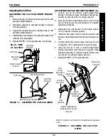
Depth
Adjustment
Bracket
Hex Head
Screws
(T-Nuts are
not shown)
Outer Rail
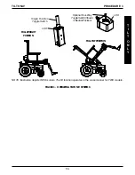
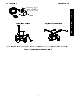
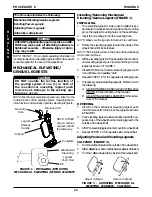
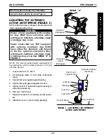
ADJUSTING THE CALF PAD HEIGHT
(FIGURE 13)
1. Loosen, but DO NOT remove, the two (2) hex head
screws that secure depth adjustment bracket to the
T-nuts.
2. Slide the calf pad assembly with T-nuts up or down
in the channel to desired position.
3. Holding the calf pad assembly into position, tightly
secure the hex screws to the T-nuts.
4. Repeat STEPS 1-3 for opposite side, if necessary.
FIGURE 13 - ADJUSTING THE CALF PAD HEIGHT
Channel
PROCEDURE 8
RIGGINGS
R
I
G
G
I
N
G
S
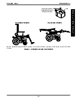
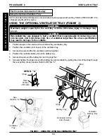
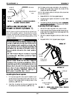
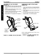
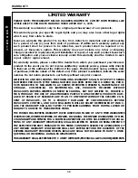
Adjusting the Length for Power Legrest
(FIGURE 14)
1. Loosen, but do not remove, the length adjustment
button screw (screw also secures lower end of
shroud).
2. Slide footplate with outer cover up or down to de-
sired position.
3. Securely tighten length adjustment button screw.
4. Repeat STEPS 1-3 for remaining legrest.
FIGURE 14 - ADJUSTING THE LENGTH FOR
POWER LEGREST
Button
Screw
Outer Cover
NOTE: Length adjustment screw is from 15-1/2-
inches to 20-inches.
Summary of Contents for Basic Tilt
Page 31: ...31 NOTES NOTES N O T E S ...


