background image

27

PROCEDURE  9

ARMRESTS

A

R

M

R

E

S

T

S

This Procedure Includes the Following:
Reclining Armrests

WARNING

After ANY adjustments, repair or service and BE-
FORE use, make sure all attaching hardware is
tightened securely - otherwise injury or dam-
age may result.

Make sure armrests are locked securely
in place BEFORE using the wheelchair.

Pinch points exist on the armrests.

NOTE: For complete operating information on Non-Re-

clining Armrests, refer to the owner's manual supplied for

the base of the wheelchair.

RECLINING ARMRESTS

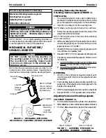
Removing Armrests (FIGURE 1)

1. Lift the armrest release lever at the front of the wheel-

chair to the unlocked (horizontal) position.

2. Lift UP on the armrest and remove from the front arm

socket.

3. Press the release button at the rear of the armrest IN.
4. While holding the release button IN, remove the arm-

rest from the seat frame.

Installing Armrests (FIGURE 1)

1. Position the armrest on the seat frame as shown in

FIGURE 1.

2. Press the release button at the rear of the armrest IN.
3. While holding the release button IN, slide the armrest

onto the seat frame.

4. Make sure the armrest release lever is in the unlocked

(horizontal) position.

5. Install the armrest into the front socket.
6. Push the armrest release lever down into the locked

(vertical) position.

Adjusting Armrest Height (FIGURE 2)

1. Make sure the seating system is in the full upright posi-

tion. Refer to OPERATING RECLINE ONLY SYS-

TEMS in PROCEDURE 4


of this manual or OPER-

ATING TILT/RECLINE SYSTEMS


in PROCEDURE 5

of this manual.

2. Remove the socket bolt and locknut that secure the

front of the upper armrest to the lower armrest.

3. Loosen, but do not remove the two (2) socket screws

and T-nuts that secure the rear of the recliner armrest

to the back cane.

4. Refer to the chart below and adjust the armrest to the

desired height for the user.

Jÿ

HOLE #:

1 2

3

4

5 6

Armrest Height

(in inches)

11 12 13 14 15 16

Jÿ

Front armrest mounting holes are numbered from bot-

tom to top for reference only. (There are no numbers on the

armrests.)

NOTE: The armrests can be at different heights to accom-

modate the user.

5. Reinstall the socket bolt through the mounting hole

determined in STEP 4.

6. Reinstall the locknut and tighten securely.
7. While holding the armrest level, tighten the two (2)

socket screws and T-nuts securely.

8. Repeat STEPS 2-7 for the opposite side if necessary.

FIGURE 2 - ADJUSTING ARMREST HEIGHT

FIGURE 1 - REMOVING/INSTALLING

ARMRESTS

LOCKED (DOWN - VERTICAL)

UNLOCKED (UP-

HORIZONTAL)

Armrest

Release

Lever

Release

Button

Armrest

Locknut

Socket

Bolt

Socket

Screws/

T-Nuts

Height

Adjustment

Holes

Back

Cane

Summary of Contents for Basic Tilt

Page 1: ...ator And Maintenance Manual DEALER THIS MANUAL MUST BE GIVEN TO THE USER OF THE WHEELCHAIR USER BEFORE USING THIS WHEELCHAIR READ THIS MANUAL AND SAVE FOR FUTURE REFERENCE Tilt Recline Tilt Recline Seating Systems ...

Page 2: ... IS SUBJECT TO CHANGE WITHOUT NOTICE SEATING SYSTEM WHEELCHAIR USER As a manufacturer of wheelchairs and seating systems Invacare endeavors to supply a wide variety of wheelchairs and seating systems to meet many needs of the user However final selection of the type of wheelchair and seating system to be used by an individual rests solely with the user and his her healthcare professional capable o...

Page 3: ...ROCEDURE 4 RECLINE ONLY 14 OPERATING RECLINE SYSTEMS ONLY 14 PROCEDURE 5 TILT RECLINE 16 OPERATINGTILT RECLINE SYSTEMS 16 PROCEDURE 6 VENTILATOR TRAY 18 USINGTHE OPTIONALVENTTRAY 18 PROCEDURE 7 SHEAR REDUCTION 19 OPTIONAL VERNIER SHEAR 19 PROCEDURE 8 RIGGINGS 20 MECHANICALELEVATING GENIUSLEGRESTS 20 INSTALLING REMOVINGTHEPOWEREDLEGS 22 ADJUSTING THE POWER LEGRESTS 23 PROCEDURE 9 ARMRESTS 27 RECLIN...

Page 4: ...em Armrests TiltOnly Recline Only and Tilt Recline Systems Legrests Headrests 16 to 22 inches In 1 inch increments 16 to 22 inches In 1 inch increments 20 to 26 inches In 1 inch increments 20 to 25 inches In 1 inch increments 90 o to 115 o in 5 o increments 0 o SeatAngle 0 o to45 o 5 o SeatAngle 5 o to50 o 0 o SeatAngle 0 o to45 o 5 o SeatAngle 5 o to50 o 0 o SeatAngle 90 o to 175 o 5 o SeatAngle ...

Page 5: ...NOT lean over the top of the back upholstery to reach objects from behind as this may cause the seating system wheelchair to tip over DO NOT shift your weight or sitting position toward the direction you are reach ing as the seating system wheelchair may tip over DO NOT operate the seating system while on an incline DO NOT operate the seating system while the wheelchair is moving TILT ONLY SYSTEMS...

Page 6: ...use bodily harm or damage to the seating system wheelchair DO NOT use parts accessories or adapters other than those authorized by Invacare DO NOT leave the power ON when entering or exiting your seating system wheelchair DO NOT attempt to lift the seating system wheelchair by lifting on any remov able detachable parts Lifting by means of any removable detachable parts of a seating system wheelcha...

Page 7: ...can resist EMI up to a certain intensity This is called its immunity level The higher the immunity level the greater the protection At this time current technology is capable of achieving at least a 20 V m immunity level which would provide useful protec tion from the more common sources of radiated EMI There are a number of sources of relatively intense electromagnetic fields in the everyday envi...

Page 8: ... of unintended brake release or powered wheelchair movement which could re sult in serious injury 1 Do not operate hand held transceivers transmitters receivers such as citi zens band CB radios or turn ON personal communication devices such as cellular phones while the powered wheelchair is turned ON 2 Be aware of nearby transmitters such as radio or TV stations and try to avoid coming close to th...

Page 9: ...l chair any further than the length of the armrests Make surethecastersarepointingintheforwardpositionwhen ever you lean forward This can be achieved by advanc ing the wheelchair and then reversing it in a straight line Coping With Everyday Obstacles Coping with the irritation of everyday obstacles can be alleviated somewhat by learning how to manage your wheelchair Keep in mind your center of gra...

Page 10: ...ide the seat to which you are transferring with the casters aligned parallel with the object Engage motor locks Shift body weight into seat with transfer During independent transfer little or no seat platform will be beneath you Use a transfer board if at all pos sible Reaching Bending Backwards WARNING DO NOT lean over the top of the back upholstery This will change your center of gravity and may...

Page 11: ...troubleshootinginformation andexplanationoferrorcodes Wheelchair Power ON but does not drive Seating system not functioning System tilted beyond drive lock out angle Low Batteries Faulty electrical connection Blown Fuse SYMPTOM PROBABLE SOLUTIONS CAUSE Tilttoneutral upright position ContactDealer Invacare for Service Charge batteries Checkallconnections Contact Dealer Invac are for Service Replace...

Page 12: ...tchwilllight NOTE Thetiltanglerangeisfrom0 o to45 o witha0 o seat to floor angle and 5 o to50 o with a 5 o seat to floor angle Single Function Toggle Switch INCREASING TILT ANGLE 1 Make sure the wheelchair is on a level surface 2 Pull single function toggle switch back towards rear of the wheelchair until the desired angle is achieved DECREASING TILT ANGLE 1 Pushthesinglefunctiontoggleswitchforwar...

Page 13: ...ION LED Optional Four Way ToggleSwitch Shown in Neutral Position LED Single Function Toggle Switch FULL UPRIGHT POSITION NOTE Illustration depicts RWD models The tilt function operates in the same manner for FWD models T I L T O N L Y TILT ONLY PROCEDURE 3 ...

Page 14: ...uredesignedtopreventthewheel chair from being driven while in any recline back angle combinationover20o RELATIVETOTHEVERTICALPO SITION When the drive lock out feature has been acti vated the LED on the four way toggle switch will light Increasing Decreasing Recline Angle NOTE The recline angle range is from 95o to 175o with a 5o seat to floor angle The recline angle range is from 90o to 175o with ...

Page 15: ... UPRIGHT POSITION FULL RECLINE POSITION LED Optional Four Way ToggleSwitch Shown in Neutral Position NOTE Illustration depicts RWD models The recline function operates in the same manner for FWD models R E C L I N E O N L Y RECLINE ONLY PROCEDURE 4 ...

Page 16: ...ggleswitchforwardtowardsthefront ofthewheelchairuntilthedesiredtiltangleisachieved NOTE If the wheelchair is equipped with switch op tions scan to the correct ECU or Auxiliary Mode and activate the control device in the correspond ing forward direction to operate the tilt function Refer to the MKIV owner s manual part number 1043576 for complete switch option operating instructions 3 Release four ...

Page 17: ... Way Toggle Switch Shown in Neutral Position LED FULL UPRIGHT POSITION TILT RECLINE COMBINATION NOTE Illustration depicts RWD models The tilt recline function operates in the same manner for FWD models T I L T R E C L I N E TILT RECLINE PROCEDURE 5 ...

Page 18: ...of the strap through the rear portion of each buckle Refer to DETAIL A FIGURE 1 USING THE OPTIONAL VENTILATOR TRAY USING THE OPTIONAL VENTILATOR TRAY FIGURE 1 WARNING Maximum weight capacity for the vent tray is 40 lbs Otherwise injury or damage may occur CAUTION This ventilator tray was designed to hold a ventilator that is approximately 13 inches long 14 1 2 inches wide and 9 3 4 inches high Use...

Page 19: ...k of the seating system MUST be returned to original position BEFORE the degree of recline is changed increased or decreased Otherwise the relation ship between Vernier Shear Reduction VSR and the recline function of the seating sys tem will change possibly resulting in injury to the user 1 Make sure the wheelchair is on a level surface 2 Note the current position of the back SHEAR REDUCTION This ...

Page 20: ...nius Legrests FIGURE 1 INSTALLING 1 Turn elevating legrest to side open footplate is per pendicular to wheelchair and position the mounting pin on the legrest mounting holes on the seat frame 2 Insertthemountingpinintothemountinghole NOTE Makesurethelegrestsitsflushontheseatframe 3 Rotate the elevating legrest toward the inside of the wheelchairuntilitlocksinplace NOTE Thefootplatewillbeontheinsid...

Page 21: ...x Bolt and Locknut Hex Bolt Calfpad Spacer Locknut Adjustment Bracket Adjustment Bracket Channel FOOTPLATE HEIGHT FIGURE 3 NOTE Thefollowingprocedureshouldbeperformedwith theuserinthewheelchair 1 Loosen but do not remove the bolt and locknut that securethelowerlegrestassemblytotheupperlegrest assembly 2 Movethelowerlegrestassemblytothedesiredposi tion for the user 3 Whileholdingthelowerlegrestinpo...

Page 22: ...chair and position the mount ing pin on the legrest with mounting holes on the seat frame DETAIL A 2 Insert the mounting pin of power legrest into the mounting hole of the seat frame DETAIL A PROCEDURE 8 RIGGINGS R I G G I N G S FIGURE 6 ADJUSTING GENIUS LEGRESTS LEGREST HEIGHT DEPTH Button Screw Adjustment Link Washer Legrest Support Washer Removing the Power Legrests 1 Disconnect power legrests ...

Page 23: ...e seat at 35 or higher Adjusting the Footplate WARNING DO NOT remove heel loops without providing some other adequate means of support otherwise personal injury may occur ADJUSTING THE FOOTPLATE HEIGHT FIGURE 8 NOTE The following procedure should be performed with the user in the wheelchair NOTE T nuts ride in the channels of the exterior interior rails of the power legrests Refer to FIGURE 8 1 Lo...

Page 24: ...ing Holes Set Screw Direction of Rotation Footplate Clamp Pivot Hinge Footplate Barrel Nuts Flush Head Screws Footplate Footplate Clamp FIGURE 10 ADJUSTING THE FOOTPLATE ANGLE 4 Repeat STEPS 1 3 for opposite side if necessary 5 For additional angle adjustment perform the following FIGURE11 A Loosen the set screw B Rotatefootplateupordowntodesiredposition C Retighten set screw DETAIL A DETAIL B PRO...

Page 25: ...nting screws securely 7 Repeat STEPS 1 6 for opposite side FIGURE 12 ADJUSTING THE CALF PAD DEPTH Calf Bracket Locking Hex Nut Depth Adjustment Bracket Depth Adjustment Holes NOTE Calf pad not shown for clarification purposes only Depth Adjustment Bracket Hex Head Screws Flat Head Mounting Screw Mounting Channel Adjusting the Calf Pad ADJUSTING THE CALF PAD WIDTH FIGURE 11 1 Removethetwo 2 buttonh...

Page 26: ... T nuts 4 Repeat STEPS 1 3 for opposite side if necessary FIGURE 13 ADJUSTING THE CALF PAD HEIGHT Channel PROCEDURE 8 RIGGINGS R I G G I N G S Adjusting the Length for Power Legrest FIGURE 14 1 Loosen but do not remove the length adjustment button screw screw also secures lower end of shroud 2 Slide footplate with outer cover up or down to de sired position 3 Securely tighten length adjustment but...

Page 27: ... 6 Push the armrest release lever down into the locked vertical position Adjusting Armrest Height FIGURE 2 1 Makesuretheseatingsystemisinthefulluprightposi tion Refer to OPERATING RECLINE ONLY SYS TEMS in PROCEDURE 4 of this manual or OPER ATINGTILT RECLINESYSTEMSinPROCEDURE5 of this manual 2 Remove the socket bolt and locknut that secure the front of the upper armrest to the lower armrest 3 Loose...

Page 28: ...E 2 1 Remove the three 3 socket screws that secure the headrest to the headrest mounting bracket 2 Position the new headrest on the headrest mounting bracket and secure with the existing three 3 socket screws 3 Ifnecessary adjusttheheight depthordirectionofthe headrest RefertoADJUSTINGHEADRESTHEIGHT orADJUSTINGHEADRESTDEPTH DIRECTIONin this procedure of the manual Headrest Stop Set Screw REMOVING ...

Page 29: ...ch is factory preset is 1 4 inch off of the ground FIGURE 1 ADJUSTING THE EXTENDED ACTIVE ANTI TIPPERS Ground Floor 1 4 inch Block Extended Anti tip Assembly Locknut B Locknut A Locknut C Bearings Dust Cover is placed here 1 Loosen locknut C B and A 2 Lift anti tipper place 1 4 inch block underneath wheel 3 Tighten locknut Aupward against bearing 4 Tighten locknut B upward against locknut A 5 Tigh...

Page 30: ...ry without our prior consent LIMITATIONS AND EXCLUSIONS THE FOREGOING WARRANTY SHALL NOT APPLY TO SERIAL NUMBERED PRODUCTS IF THE SERIAL NUMBER HAS BEEN REMOVED OR DEFACED PROD UCTS SUBJECTED TO NEGLIGENCE ACCIDENT IMPROPER OPERATION MAINTENANCE OR STORAGE COMMERCIAL OR INSTITUTIONAL USE PRODUCTS MODIFIED WITHOUT INVACARE S EXPRESS WRITTEN CONSENT INCLUDING BUT NOT LIMITED TO MODIFICA TION THROUGH...

Page 31: ...31 NOTES NOTES N O T E S ...

Page 32: ...atheson Blvd E Invacare is a registered trademark of Invacare Corporation Elyria Ohio USA Unit 8 Mississauga Ontario Yes you can is a trademark of Invacare Corporation 44036 2125 L4Z 4G4 Canada 2003 Invacare Corporation 800 333 6900 800 668 5324 Part No 1090207 Rev 1 04 03 ...

Reviews: