background image

Formula™ CG Tilt Manual Center Mount Front Rigging

6

Part No 1145733

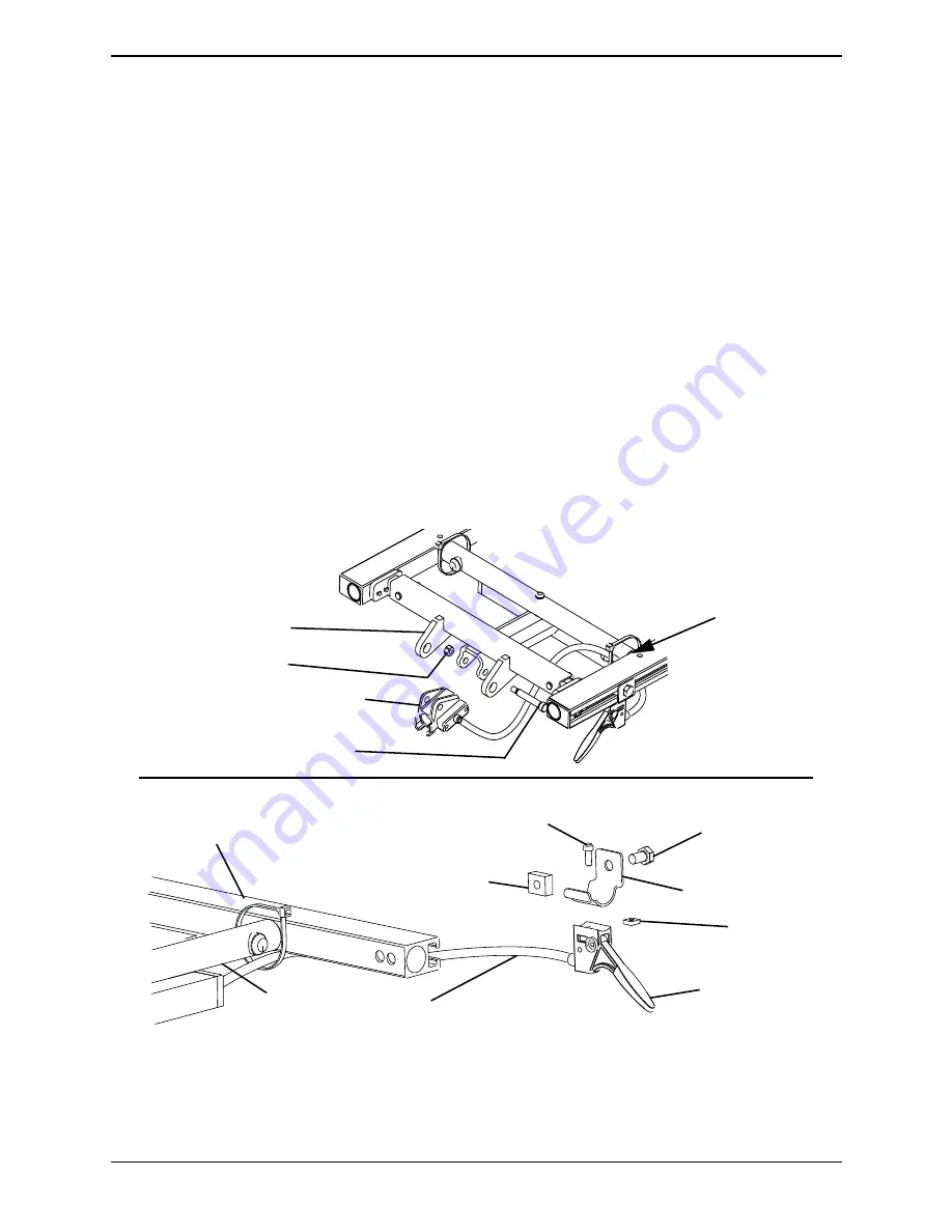
Mounting the Release Lever Assembly to the Seat 
Frame

NOTE:


For


this


procedure,


refer


to


FIGURE 4.

NOTE:


The


release


lever


assembly


consists


of


the


release


handle,


cable


and


ratchet


housing.

1. Insert


the


glide


bearing


into


the


ratchet


housing.

2. Using


the


two


10

32


X


.69


pan


head


screws


and


#10


lock


washers,


secure


the


cable/brake


assembly


to


the


ratchet


housing.


Torque


to


32


in

lbs.

3. Secure


the


ratchet


housing


to


the


mounting


bracket


on


the


center


mount


front


rigging


support


with


the


5/16


X


1.625


inch


socket


head


shoulder


screw


and


1/4

20


inch


locknut


provided


(Detail


“A”).


Torque


to


79


in

lbs.

4. Secure


the


release


handle


to


the


release


handle


mounting


bracket


with


the


10

32


X


.50


inch


socket


head


screw


and


10

32


inch


square


nut.


Securely


tighten.

5. Secure


the


release


handle


mounting


bracket


to


the


T

nut


in


the


side


rail


with


the


5/16

18


X


.50


inch


hex


head


bolt.


Torque


to


13


ft

lbs.

6. Tie

wrap


cable


as


shown


in


Detail


“A”.

FIGURE 4   

Mounting the Release Lever Assembly to the Seat Frame

5/16 X 1.625 inch Socket 

Head Shoulder Screw

Ratchet Housing

1/4-20 inch Locknut

Center Mount Front 

Rigging Support

NOTE:


Seat


pan


not


shown


for


clarity.

DETAIL “A”

Seat Frame

10-32 inch 

Square Nut

Release Handle

Release Handle 

Mounting Bracket

Tie-Wrap the 

Cable Here

10-32 X .50 inch 

Socket Head Screw

T-Nut

(Shown exploded 

for clarity)

Side Rail

Cable

5/16-18 X .50 inch 

Hex Head Bolt

Summary of Contents for CTMT-F

Page 1: ...unable to understand the warnings cautions and instructions contact a healthcare professional dealer or technical personnel if applicable before attempting to install this equipment otherwise injury...

Page 2: ...Bracket Jr 1 7 1121728 Weldment Support Pan Seat 2 7 1147104 Weldment Support Pan Seat Jr 2 8 1146347 Plug Support 2 9 1008495 Screw 20 X 1 50 Socket Button Head Cap 1 10 1125775 Black Mounting Bracke...

Page 3: ...e side 4 On the side of the wheelchair where the release handle will be mounted remove the side rail end cap NOTE T nut will be installed on the same seat rail that the release lever will be mounted t...

Page 4: ...xtensions according to Detail A D Using the two 20 X 1 25 inch socket head screws and 20 inch locknuts secure the two support extensions to the center mount rigging support 4 Secure the left side of t...

Page 5: ...23W 24W 20 X 1 50 inch Button Head Screw 20 inch Locknut Plug Button 20 X 1 25 inch Socket Head Screws Spacer Seat Frame Center Mount Rigging Support Side Rail NOTE Seat pan and existing button head...

Page 6: ...nut provided Detail A Torque to 79 in lbs 4 Secure the release handle to the release handle mounting bracket with the 10 32 X 50 inch socket head screw and 10 32 inch square nut Securely tighten 5 Sec...

Page 7: ...pulling the center mount footrest out of the mounting bracket of the seat frame Installing 1 Engage the release lever with one hand hold the center mount footrest with the other and insert the center...

Page 8: ...ion tube FIGURE 6 Adjusting the Height of the Manual Center Mount Footrest Adjusting the Angle of the Manual Center Mount Footrest WARNING While the wheelchair is moving minimum ground clearance for t...

Page 9: ...refer to FIGURE 9 NOTE The tension can be adjusted to increase or decrease the rotation effort of the flip up footplates 1 Loosen the mounting screw on the front rigging angle hinge to decrease the r...

Page 10: ...h as shown in FIGURE 10 4 Using the mounting screw nylon washer washer and wave washer secure the footplate to the extension tube 5 Repeat STEPS 1 and 4 for the other footplate FIGURE 10 Adjusting the...

Page 11: ...he serial number when applicable as identification within thirty 30 days of return authorization date DO NOT return products to our factory without our prior consent C O D shipments will be refused pl...

Page 12: ...4 Canada 800 668 5324 2010 Invacare Corporation All rights reserved Republication duplication or modification in whole or in part is prohibited without prior written permission from Invacare Trademark...

Reviews: