background image

Formula™ CG Tilt Manual Center Mount Front Rigging

8

Part No 1145733

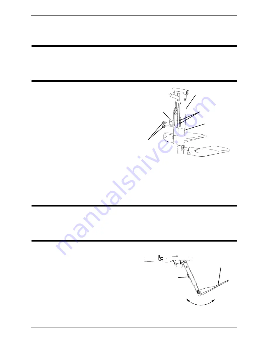
Adjusting the Height of the Manual Center Mount 
Footrest


WARNING

While the wheelchair is moving, minimum ground clearance for the front rigging is 

three inches. If the wheelchair is not moving, the front rigging MUST maintain a 

minimum of one inch ground clearance - otherwise personal injury and damage may 

result.

NOTE:


For


this


procedure,


refer


to


FIGURE 6.

1. Loosen


the


two


mounting


screws


that


secure


the


button


head


cleat


to


the


extension


housing.

2. Adjust


the


footrest


extension


tube


to


the


desired


height.

3. Secure


the


extension


tube


to


the


desired


height


with


the


button


head


cleat


and


mounting


screws.


Securely


tighten.

4. Repeat


STEPS


1

3


for


the


other


extension


tube.

FIGURE 6   

Adjusting the Height of the 

Manual Center Mount Footrest

Adjusting the Angle of the Manual Center Mount 
Footrest


WARNING

While the wheelchair is moving, minimum ground clearance for the front rigging is 

three inches. If the wheelchair is not moving, the front rigging MUST maintain a 

minimum of one inch ground clearance - otherwise personal injury and damage may 

result.

NOTE:


For


this


procedure,


refer


to


FIGURE 5


on


page 7


and


FIGURE 7.

1. Engage


the


release


lever


with


one


hand


(not


shown)


and


move


the


center


mount


footrest


to


the


desired


angle


with


the


other


hand.

NOTE:


Refer


to


FIGURE 5


for


the


location


of


the


release


lever.

2. Disengage


the


release


lever


(not


shown)


to


lock


the


center


mount


footrest


in


the


new


position.

FIGURE 7   

Adjusting the Angle of the 

Manual Center Mount Footrest

Extension Housing

Extension 

Tube

Mounting 

Screws

Extension Tube 

Mounting Holes

Button 

Head Cleat

Footplate

Center Mount 

Footrest

Summary of Contents for CTMT-F

Page 1: ...unable to understand the warnings cautions and instructions contact a healthcare professional dealer or technical personnel if applicable before attempting to install this equipment otherwise injury...

Page 2: ...Bracket Jr 1 7 1121728 Weldment Support Pan Seat 2 7 1147104 Weldment Support Pan Seat Jr 2 8 1146347 Plug Support 2 9 1008495 Screw 20 X 1 50 Socket Button Head Cap 1 10 1125775 Black Mounting Bracke...

Page 3: ...e side 4 On the side of the wheelchair where the release handle will be mounted remove the side rail end cap NOTE T nut will be installed on the same seat rail that the release lever will be mounted t...

Page 4: ...xtensions according to Detail A D Using the two 20 X 1 25 inch socket head screws and 20 inch locknuts secure the two support extensions to the center mount rigging support 4 Secure the left side of t...

Page 5: ...23W 24W 20 X 1 50 inch Button Head Screw 20 inch Locknut Plug Button 20 X 1 25 inch Socket Head Screws Spacer Seat Frame Center Mount Rigging Support Side Rail NOTE Seat pan and existing button head...

Page 6: ...nut provided Detail A Torque to 79 in lbs 4 Secure the release handle to the release handle mounting bracket with the 10 32 X 50 inch socket head screw and 10 32 inch square nut Securely tighten 5 Sec...

Page 7: ...pulling the center mount footrest out of the mounting bracket of the seat frame Installing 1 Engage the release lever with one hand hold the center mount footrest with the other and insert the center...

Page 8: ...ion tube FIGURE 6 Adjusting the Height of the Manual Center Mount Footrest Adjusting the Angle of the Manual Center Mount Footrest WARNING While the wheelchair is moving minimum ground clearance for t...

Page 9: ...refer to FIGURE 9 NOTE The tension can be adjusted to increase or decrease the rotation effort of the flip up footplates 1 Loosen the mounting screw on the front rigging angle hinge to decrease the r...

Page 10: ...h as shown in FIGURE 10 4 Using the mounting screw nylon washer washer and wave washer secure the footplate to the extension tube 5 Repeat STEPS 1 and 4 for the other footplate FIGURE 10 Adjusting the...

Page 11: ...he serial number when applicable as identification within thirty 30 days of return authorization date DO NOT return products to our factory without our prior consent C O D shipments will be refused pl...

Page 12: ...4 Canada 800 668 5324 2010 Invacare Corporation All rights reserved Republication duplication or modification in whole or in part is prohibited without prior written permission from Invacare Trademark...

Reviews: