background image

TABLE OF CONTENTS

Invacare Mobile Recliners

4

Part No. 1141494

TABLE OF CONTENTS

SECTION 5— MAINTENANCE .......................................................... 21

Replacing the Back Cushion...................................................................................................................21

Model IH6074A and IH6065 series .................................................................................................21

Model IH6077A ....................................................................................................................................22

Replacing the Footrest Cushion............................................................................................................22
Replacing the Recline Mechanism Guard ............................................................................................23
Replacing the Elbow Pads - Model IH6077A Only ...........................................................................24
Adjusting Gas Spring Recline Cylinder Assembly - Model IH6077A Only..................................24
Replacing the Release Handle and Cable Assembly - Model IH6077A Only .............................25
Replacing Position Lock Lever - Models H6074A and IH6065 Series Only ...............................26

Removing Position Lock Lever .........................................................................................................26

Installing Position Lock Lever............................................................................................................26

Replacing Casters .....................................................................................................................................27

Replacing Caster Assembly................................................................................................................27

Replacing Caster Wheels ...................................................................................................................27

Replacing Plunger Release Knob ...........................................................................................................28
Removing/Installing the Side Panel........................................................................................................28
Removing Side Panels ..............................................................................................................................28

Installing Side Panel..............................................................................................................................28

Replacing the Armrest Cushion............................................................................................................29

Removing Armrest Cushion..............................................................................................................29

Installing Armrest Cushion ................................................................................................................29

Cleaning the Upholstery .........................................................................................................................29

LIMITED WARRANTY  ..................................................................... 32

REGISTER YOUR PRODUCT

The benefits of registering include:
1. Safeguarding your investment.
2. Ensuring long-term maintenance and servicing of your product.
3. Receiving updates with product information, maintenance tips and industry news.

Register ONLINE at warranty.invacare.com

Please have your model number and purchase date available to complete your registration.

Summary of Contents for Deluxe Three-Position IH6065

Page 1: ...E using this product read this manual and save for future reference For more information regarding Invacare products parts and services please visit www invacare com Invacare Mobile Recliners Three Position Recliner Model IH6074A Deluxe Three Position Recliner Model IH6065 series Clinical Recliner Model IH6077A ...

Page 2: ...YOU ARE UNABLE TO UNDERSTAND THE WARNINGS CAUTIONS OR INSTRUCTIONS CONTACT A HEALTHCARE PROFESSIONAL DEALER OR TECHNICAL PERSONNEL BEFORE ATTEMPTING TO USE THIS EQUIPMENT OTHERWISE INJURY OR DAMAGE MAY OCCUR ACCESSORIES WARNING INVACARE PRODUCTS ARE SPECIFICALLY DESIGNED AND MANUFACTURED FOR USE IN CONJUNCTION WITH INVACARE ACCESSORIES ACCESSORIES DESIGNED BY OTHER MANUFACTURERS HAVE NOT BEEN TEST...

Page 3: ...ne Option Operated by an Attendant 9 SECTION 2 SAFETY INSPECTION 10 Safety Inspection Checklists 10 SECTION 3 ASSEMBLY 12 Assembling the Recliner 12 Assembling Models IH6074A and IH6065 series 12 Assembling Model IH6077A 13 SECTION 4 OPERATION 15 Reclining the Chair 15 Models IH6074A and IH6065 series 15 Model IH6077A 16 Positioning the Articulating Headrest 17 Locking Unlocking the Rear Wheels 18...

Page 4: ...k Lever 26 Installing Position Lock Lever 26 Replacing Casters 27 Replacing Caster Assembly 27 Replacing Caster Wheels 27 Replacing Plunger Release Knob 28 Removing Installing the Side Panel 28 Removing Side Panels 28 Installing Side Panel 28 Replacing the Armrest Cushion 29 Removing Armrest Cushion 29 Installing Armrest Cushion 29 Cleaning the Upholstery 29 LIMITED WARRANTY 32 REGISTER YOUR PRODU...

Page 5: ... operate the recliner The legrest falls down upon closing so that a child could possibly be injured When unoccupied ensure the legrest is down Keep hands and feet clear of mechanism 1143177 Rev A 4 25 06 DO NOT press down or stand on the footrest 1143178 Rev A 4 25 06 NOTE Model IH6074A shown IH6065 series and IH6077A labels are in the same locations ...

Page 6: ...chairs for occupant use within any type of vehicle It is Invacare s position that users of Mobile Recliners should be transferred into appropriate seating in vehicles for transportation and use be made of the restraints made available by the auto industry To date Invacare does not have nor do we have any say in the recommendation of the manufacture of Mobile Recliner transportation systems MAINTEN...

Page 7: ...es 74 inches SEAT WIDTH 19 inches Petite 16 inches Adult 18 inches Wide 22 inches Drop Arm 18 inches 31 inches SEAT DEPTH 19 inches 19 inches 19 inches SEAT TO BACK HEIGHT 32 inches 32 inches 32 inches SEAT TO FLOOR HEIGHT 21 1 2 inches 21 inches 22 inches SEAT ANGLE RANGE 13 38 11 38 14 35 BACK ANGLE RANGE 28 54 29 55 29 77 OVERALL TRAY LENGTH AND WIDTH 25 x 15 inches 25 x 15 inches 10 x 19 inche...

Page 8: ...als even though treated with flame retardant can ignite when exposed to open flame Rear caster wheels MUST be locked during user transfer to or from recliner and while tilting and or reclining or inclining sitting up Ensure that casters are free of debris Casters and axle bolts require inspection every six months to check for tightness and wear DO NOT enter or exit the recliner when footrest is el...

Page 9: ... for use in conjunction with Invacare accessories Accessories designed by other manufacturers have not been tested by Invacare and are not recommended for use with Invacare products Weight Limitation The weight limitation for Invacare Mobile Recliners is 250 lbs 113 6 kg The weight limitation for model IH6065WD Wide Recliner is 400 lbs 181 44 kg The tray for models IH6074A IH6065A and IH6077A has ...

Page 10: ...nsure that the recliner rolls straight no excessive drag or pull to one side Ensure seat back and or armrest upholstery have no rips and do not sag Replace if necessary Ensure that the seat upholstery is fastened to the seat frame Clean seat upholstery and armrests Inspect caster assembly to ensure it has proper tension when caster is spun Caster should come to a gradual stop Loosen tighten caster...

Page 11: ...spun Caster should come to a gradual stop Loosen tighten caster locknut if wheel wobbles noticeably or binds to a stop Inspect for any loose hardware on the recliner FOR IH6077A ONLY Ensure that the trigger releae cables completely release and the handles return when released Inspect Adjust Periodically Ensure recliner rolls straight no excessive drag or pull to one side Ensure seat back and or ar...

Page 12: ...3 1 on page 13 1 Remove back frame with back cushion from its carton 2 Lock the rear casters Work from the rear of the recliner base NOTE Ensure that footrest is in closed position before installing the back frame with cushion 3 Lift the chair back in an upright position behind the rear seat cross brace 4 Slide the back tubes into the open tube ends of the rear seat cross brace 5 Lift the plastic ...

Page 13: ...age 14 6 Insert a clevis pin through back assembly bracket and seat frame and secure with a retaining ring as shown in Detail ʺAʺ in FIGURE 3 2 on page 14 Repeat for opposite side 7 Align the gas spring bracket with the holes of the mounting bracket on the center of the seat frame 8 Insert a clevis pin through the gas spring bracket and through the mounting bracket on the seat frame and secure wit...

Page 14: ...IGURE 3 2 Assembling the Recliner Assembling Model IH6077A DETAIL A POSITIONING DETAIL B REAR VIEW DETAIL C SIDE PANEL Retaining Ring Clevis Pin Seat Frame Push Buttons Side Panel Back Assembly Bolt D Bolt C Elbow Pad Elbow Pad Bracket Actuator Gas Spring Bracket Side View See Detail A See Detail A Bolt A Bolt B ...

Page 15: ...els IH6074A and IH6065 series User Recline NOTE For this procedure refer to FIGURE 4 1 NOTE The chair cannot recline if the recline lock bar is engaged An assistant must first swing recline lock bar up to the chair back and lock into position 1 While seated in the recliner grip the armrests and simultaneously lean body weight back and push forward with your arms until a recline position reached NO...

Page 16: ... Assisted Recline Model IH6077A NOTE The position lock lever is not available on model IH6077A User Recline NOTE For this procedure refer to FIGURE 4 3 1 While seated in the recliner grip the armrests and simultaneously lean body weight back and push forward with your arms until a recline position is reached NOTE The footrest assembly will elevate automatically as the chair is reclined NOTE The oc...

Page 17: ...hand Detail A 4 Lower the chair back slowly down into Shock position Detail B 5 Release the gas spring handle NOTE If the cylinder does not unlock when the lever is actuated or remains permanently unlocked when the lever is not actuated cable tension must be adjusted Refer to Adjusting Gas Spring Recline Cylinder Assembly Model IH6077A Only on page 24 FIGURE 4 4 Reclining the Chair Model IH6077A A...

Page 18: ...plunger release knobs on both arms and twist them turn to lock them in the open position 2 Pull the tray forward and clear from the hanger located on the side of the recliner 3 Align the alignment rods with the mounting brackets under the armrests of the recliner 4 Insert the alignment rods into the mounting brackets 5 Slide the tray to the desired position until an audbile click is heard FIGURE 4...

Page 19: ...under the armrests of the recliner 4 Insert the alignment rods into the mounting brackets 5 Slide the tray to the desired position until an audbile click is heard FIGURE 4 8 Installing Storing the Tray Model IH6065A Model IH6077A WARNING The tray has a weight limitation of 40 lbs 18 2 kg NOTE For this procedure refer to FIGURE 4 9 1 To lower tray pull out the tray and lower FIGURE 4 9 Installing S...

Page 20: ...he Tray to a Locked Position 1 Pull down on the plunger release knob below the armrests of the chair seated and push pull the tray to the desired position 2 Ensure tray locks in place To Set the Tray to Freeflow 1 Pull down on the plunger release knob below the right arm rest of the chair seated and push pull the tray to the desired position 2 Slide the plastic keeper forward and release the plund...

Page 21: ...ws that secure the back cushion to the back frame 2 Remove the four short hex screws that secure headrest bracket to the back cushion Repeat for remaining headrest bracket Installing 1 Align back cushion with the back frame 2 Install four long hex screws to secure the back cushion to the back frame Securely tighten 3 Secure the headrest bracket to the back cushion with four short hex screws 4 Secu...

Page 22: ... location as on the old back assembly Installing 1 Align new back cushion with seat and frame 2 Install four long hex screws to secure the back cushion to the back frame as shown in FIGURE 2 Securely tighten 3 Secure the headrest bracket to the back cushion with four short hex screws Securely tighten FIGURE 5 2 Replacing the Back Cushion Model IH6077A Replacing the Footrest Cushion WARNING DO NOT ...

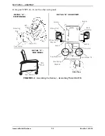
Page 23: ...ions on or around the floor before doing this 3 Remove the side panel Refer to Removing Installing the Side Panel on page 28 4 Remove four existing bolts A B C and D from side frame as shown in FIGURE 5 4 on page 24 5 Remove existing recline mechanism guard 6 Position new recline mechanism guard against the side frame with the folded edge down 7 Align holes of new recline mechanism guard with hole...

Page 24: ...h secures the cable to the back assembly 2 Remove the retaining ring from the clevis pin 3 Remove mounting bolt and locknut securing the gas spring recline cylinder to the back frame 4 Recline the back until cylinder can be removed from mounting bracket easily approximately a 45 angle 5 Remove gas spring recline cylinder 6 Loosen the locknut on the bottom of the cylinder Detail ʺAʺ 7 Hold the bott...

Page 25: ...e from the mounting bracket use care to pull straight out of V notch DO NOT remove by bending the cable Damage to the cable may occur 2 Remove cable assembly from ʺVʺ notch of the mounting bracket Detail ʺBʺ 3 Remove the mounting screw that secures the cable to the back frame 4 Remove the mounting screw which secures the release handle to the push handle Detail ʺAʺ 5 Secure new release handle to t...

Page 26: ...tion Lock Lever Models H6074A and IH6065 Series Only NOTE For this procedure refer to FIGURE 5 8 Removing Position Lock Lever 1 Remove two screws nylon washers and locknuts securing the position lock lever to the seat frame Installing Position Lock Lever 1 Secure the position lock lever to the seat frame with the two screws nylon washers and locknuts FIGURE 5 8 Replacing Position Lock Lever Models...

Page 27: ...lies Replacing Caster Wheels NOTE For this procedure refer to Detail B of FIGURE 5 9 NOTE When replacing the rear locking caster wheel note the orientation of the locking actuator and axle bolt for proper reinstallation 1 Remove axle bolt and locknut that secure the existing caster wheel to the fork 2 Remove existing caster wheel from fork 3 Install the new caster wheel into the fork 4 Install the...

Page 28: ...the frame FIGURE 5 10 Replacing Plunger Release Knob Removing Installing the Side Panel NOTE For this procedure refer to FIGURE 5 11 Removing Side Panels 1 Press the push buttons near the bottom of the right side panel 2 Hold the push buttons in while pulling the panel outward 3 Repeat STEPS 1 and 2 for the other side panel Installing Side Panel 1 Slip the top of the right side panel into the moun...

Page 29: ...ovided with cleaning product DO NOT use paint remover or any liquid brush cleaner NOTE A variety of solvents may be used to clean the upholstery on the recliner dependant upon the severity of the stain The following list should be helpful Ordinary dirt stains Clean upholstery with warm water and mild detergent to remove superficial soil Ground in dirt stains Use soft bristle brush and powdered cle...

Page 30: ...SECTION 5 MAINTENANCE Invacare Mobile Recliners 30 Part No 1141494 NOTES ...

Page 31: ...SECTION 5 MAINTENANCE Part No 1141494 31 Invacare Mobile Recliners NOTES ...

Page 32: ...HALL NOT APPLY TO SERIAL NUMBERED PRODUCTS IF THE SERIAL NUMBER HAS BEEN REMOVED OR DEFACED PRODUCTS SUBJECTED TO NEGLIGENCE ACCIDENT IMPROPER OPERATION MAINTENANCE OR STORAGE PRODUCTS MODIFIED WITHOUT INVACARE S EXPRESS WRITTEN CONSENT INCLUDING BUT NOT LIMITED TO MODIFICATION THROUGH THE USE OF UNAUTHORIZED PARTS OR ATTACHMENTS PRODUCTS DAMAGED BY REASON OF REPAIRS MADE TO ANY COMPONENT WITHOUT ...

Reviews: