background image

Invacare® Matrx® PB Elite

6

Part No 1171724

3.4

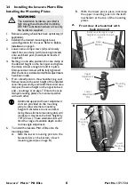
Installing the Invacare Matrx Elite

Installing the Mounting Plates

1.

Remove existing wheelchair back upholstery (if 

applicable).

2.

Establish the desired mounting plate set-

up/configuration for the user. Refer to Before 

Installation on page 5.

3.

Loosen cane clamp screws (x3) and loosely 

install the cane clamp (with mounting bracket) 

onto each back post. (Install plastic inserts if 

required).

4.

Starting on one side, position the cane clamp at 

the desired height on the back post and tighten 

the clamp screws enough to hold it in place. 

Clamps and set screws will be fully tightened 

after the back is installed and all final adjustments 

have been made.

5.

From a fixed point on the wheelchair (e.g. seat 

frame) measure the exact height of the installed 

cane clamp assembly, and install the second cane 

clamp at the same height on the opposite back 

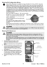
post - see image A on page 7. Ensure the cane 

clamps/mounting plates are mounted parallel 

with each other.

6.

To install the Invacare Matrx Elite onto the 

mounting plates:

A. Slide the lower mounting pins into the 

hooked slots at the bottom of each 

mounting plate (see image B).

B.

With the lower pins in place, lock/snap 

the upper mounting pins into the latch 

mechanism at the top of the mounting 

plates.

WARNING

The installation hardware provided is 

high strength and tested for durability. 

DO NOT substitute hardware. Use only 

the hardware supplied.

Additional upper and lower adjustment 

slots are provided on the mounting 

plate to allow alternate mounting 

heights if obstacles are encountered. 

Using these alternate mounting slots will 

increase or decrease the back height by 

7/8” (22 

mm

). These alternate slots will 

limit the range of available depth and/or 

recline angle adjustment.

1

2

Cane 

Clamps

Install cane clamps at equal 

heights and parallel to each 

other.

Front view of wheelchair with 

back removed

Upper 

Adjustment 

Slot

Mounting 

Plate

Lower 

Adjustment 

Slot

Upper 

Mounting 

Pin

Lower 

Mounting 

Pin

A

B

Summary of Contents for EDB

Page 1: ...o provide precise orientation within the wheelchair for optimal postural support The foam is oversized to provide extra comfort and protection The Invacare Matrx Elite back includes a movable foam lum...

Page 2: ...justed close to the rear of the client s head during transportation in order to reduce the risk of whiplash injuries The Wheelchair Tie down and Occupant Restraint System WTORS Wheelchair Tie down The...

Page 3: ...e Matrx Elite assembly onto back canes with an outside diameter greater than 1 inch or less than 3 4 inch Otherwise injury or damage may occur The mounting position of the Invacare Matrx Elite is dire...

Page 4: ...18 PBE1720 3 in 8 cm EDB1712 EDB1716 EDB1718 EDB1720 6 in 15 cm PBE1720 FB 3 in 8 cm 18 in 46 cm PBE1810 PBE1812 PBE1816 PBE1818 PBE1820 3 in 8 cm EDB1812 EDB1816 EDB1818 EDB1820 6 in 15 cm PBE1820 FB...

Page 5: ...center of gravity within the wheelchair A recessed back position can significantly reduce the rearward stability of the wheelchair Similarly a more forward back position will reduce the wheelchair s...

Page 6: ...image A on page 7 Ensure the cane clamps mounting plates are mounted parallel with each other 6 To install the Invacare Matrx Elite onto the mounting plates A Slide the lower mounting pins into the ho...

Page 7: ...re suitable for most typical wheelchair configurations The long pins are designed to allow installation onto back posts that are up to 1 25 mm wider than the width of the actual backrest Elite back wi...

Page 8: ...levers left and right to unlock the latch mechanism and release the upper pins from the mounting plates Refer to the figure Cord Release Mechanism Lift cord upward to unlock open the release levers Re...

Page 9: ...loop fasteners 4 3 One Hand Cord Release Mechanism 1 Thread the nylon cord through the holes in the latch mechanism at the top of the left and right mounting plates see image A 2 Install the cord lock...

Page 10: ...ide of the back for modification Carefully remove the cover by releasing the hook and loop fasteners along the top and bottom edge and inside of the back shell Remove the inner foam cushion from the c...

Page 11: ...icable as identification within thirty 30 days of return authorization date DO NOT return products to our factory without our prior consent C O D shipments will be refused please prepay shipping charg...

Page 12: ...wanda NY 14150 888 433 6818 Canada 84 Citation Dr Concord Ontario L4K 3C1 905 695 0134 2011 Motion Concepts All rights reserved Republication duplication or modification in whole or in part is prohibi...

Reviews: