7
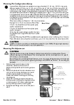
Mounting Pin Configurations/Setup
Mounting Pin Adjustment
1.
With the back secured in place on the
wheelchair, determine the amount of
adjustment required for each mounting pin (see
figure).
2.
Remove the backrest from the wheelchair and
use a wrench to loosen the flange nut on each
pin that requires adjustment. If necessary,
replace the standard mounting pins with long
mounting pins.
3.
Adjust the mounting pin depth (clockwise to
shorten/counter-clock wise to lengthen) so that
a minimum gap of 1/8” (3mm) exists between
the top of the pin and the mounting plate.
4.
Re-tighten each flange nut to secure the pins in
place.
Invacare Matrx Elite backs are available in a range of widths (12” (31 cm) - 20” (51 cm)) and 6
different heights (10” (26 cm); 12” (31 cm); 14” (36 cm); 16” (41 cm); 18” (46 cm) and 20” (51
cm)). Due to variances that exist between different wheelchair manufacturers, the depth of the
mounting pins may require some adjustment to properly fit the Invacare Matrx Elite onto the
wheelchair back posts. Refer to Mounting Pin Adjustment on page 7. Two sets of mounting pins
are supplied with every Invacare Matrx Elite (standard pins and long pins). The standard pins are
installed at the factory and are suitable for most typical wheelchair configurations. The long pins
are designed to allow installation onto back posts that are up to 1” (25 mm) wider than the width
of the actual backrest.
*Elite back widths are offered in 1” (25 mm) increments).
Example: for a 16" (41 cm) Invacare Matrx Elite:
16" (41 cm) wheelchair seat frame (back post)
width = standard pins
17" (43 cm) wheelchair seat frame (back post)
width = long pins
When the narrowest setting is used for the back,
the depth/recline range will be less than in wider
positions.
Extended Mounting Pins (EMP) are available (sold separately) to allow interfacing of our Invacare
Matrx Elite backs onto wheelchair seat frames up to 2” (5 cm) wider than the actual back width.
CAUTION
* EMP’s are only for use with our standard back sizes (for up to 300lb (136 kg) weight capacity);
EMP’s are not recommended for use in tilt applications.
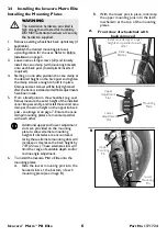
Rear View
Mounting
Pins (x 4)
Adjustable
Pin Depth
CAUTION
Improper pin set-up may cause damage to the back pan and/or the mounting plates. Ensure
sufficient spacing is provided between the mounting plates and the mounting pins (a min. gap of
1/8” (3mm) is recommended).
Ensure flange nuts are fully tightened; Failure to do so may cause damage/cracking in the back pan.
Ensure pins do not rotate when tightening the flange nuts. NEVER use Loctite® on mounting pin
hardware.
Standard
Mounting Pin
Flange Nut
Back Pan
1/8” (3 mm)
min. gap
(optional)
Long Mounting Pin
Mounting Plate


