background image

Etude Plus

Dismounting

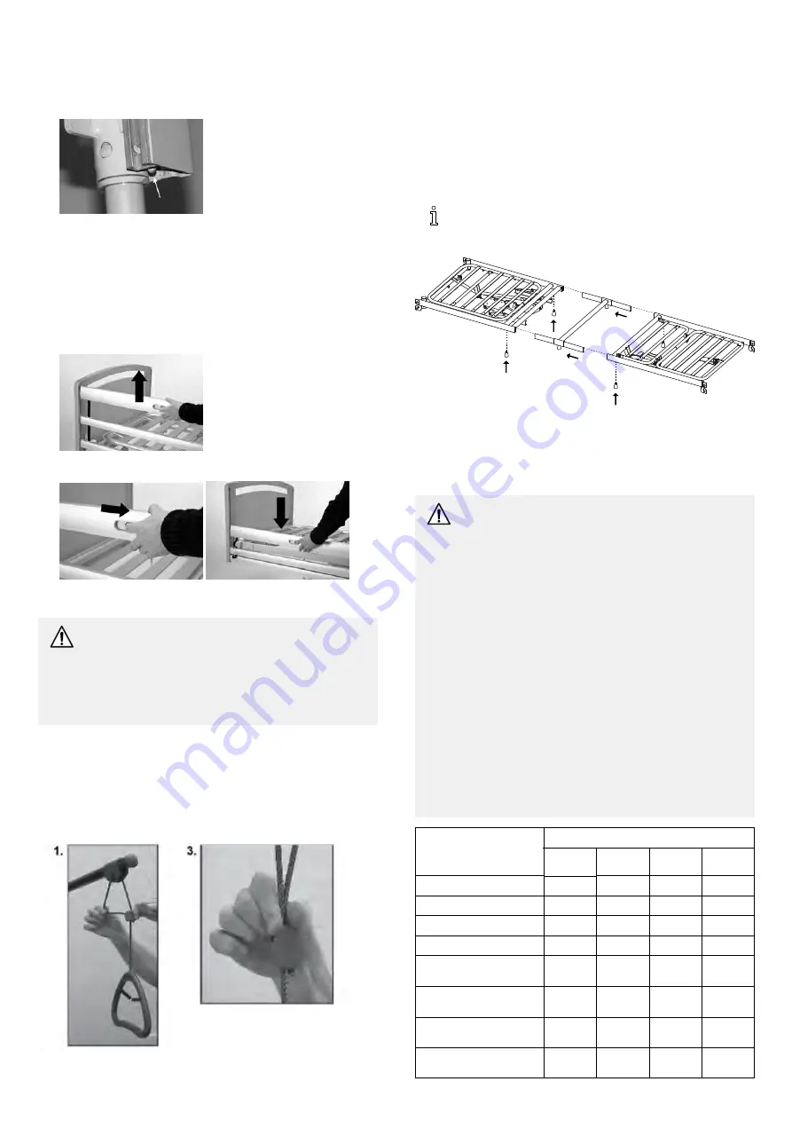
1.

Lower the side rail.

2.

Dismount one end at a time. Lift the lower bar, so that the spring
pawl is visible.

3.

Press the spring pawl with a key or a screwdriver.

4.

Hold the lower bar. Lower the side rail, until all three bars are
free of the bed end rail.

5.

Repeat points 2 to 4 when dismounting the other end of the side
rail.

Operating

As a standard, the side rails can only be locked in top position.

1.

To lock / raise to upper position:

Pull up the top side rail bar,

until the locking pin locks with an audible click

2.

To release to lower position:

Lift the top side rail bar and

press the two locking rings together and lower the side rail.

5.3 Lifting pole

WARNING!
Risk of injury

If the lifting pole is used while the handle has been turned
away from the bed, the bed can tip when the handle is
used.

Position the lifting pole in such a way that the handle

extends inwards across the bed.

Mounting

1.

Remove the plug from the lifting pole tube at the head end of the
bed where the lifting pole is to be placed.

2.

Insert the lifting pole into the lifting pole tube and fix with the
thumb screw.

Adjusting the height of the lifting pole handle

1.

Loosen the cord.

2.

The lifting handle can now be adjusted to the desired height.

3.

Press the cord together and check that the cord is locked in the
cord lock by pulling the handle.

The distance between the lifting pole and the mattress

Minimum (at 16 cm mattress)

36-59 cm

Maximum (at 10 cm mattress)

42-65 cm

5.4 Mattress support extension

For patients, taller than two meters it is recommended to
use a mattress support extension.

Fitting the mattress support extension

1.

Disassemble the bed and remove the inserts.

2.

Mount the mattress support extension between both parts of the
mattress support and reassemble the bed.

5.5 Mattress

WARNING!
Safety aspects regarding combination of side rails
and mattresses:

In order to obtain the highest possible safety level,

when using the bed in combination with side rails, it
is important to respect the minimum and maximum
measures for mattresses stated in the table.

To mitigate the possibility of the user crawling over the

top of the side rail, with the risk of severe injury due
to e.g. falling, a minimum vertical distance of 22 cm
between the top of the mattress and the top of the
side rail are to be respected. The maximum mattress
height in combination with a given side rail is stated
in the table.

To prevent head entrapment between the inside

surface of the side rail and the mattress, with the risk
of e.g. suffocation, a safety maximum space has to be
respected. When especially very thick mattresses or
soft mattresses (low density) or a combination of these
it is important to focus on this risk. The minimum
width (and length) of mattresses in combination with a
given side rail is stated in the table.

Mattress measures (in cm):

Side rail:

Min.

height

Max.

height

Min.

width

Min.

length

Scala Basic 2

10

17

85 – 90

200

Scala Basic Plus 2

10

17

85 – 90

200

Scala Medium 2

10

22

85 – 90

200

Scala Decubi 2

23

31

85 – 90

200

Line*, mattress support
platform in low position

11

22

88 – 90

200

Line*, mattress support
platform in high position

5

15

88 – 90

200

Britt V, mattress support
platform in low position

11

22

85 – 90

200

Britt V, mattress support
platform in high position

5

15

85 – 90

200

10

1567454-A

Summary of Contents for Etude Plus

Page 1: ...Invacare Etude Plus Etude Plus Etude Plus Low EN Bed User Manual This manual MUST be given to the user of the product BEFORE using this product read this manual and save for future reference...

Page 2: ...dentified by and All trademarks are owned by or licensed to Invacare Corporation or its subsidiaries unless otherwise noted This bed has been tested and approved according to IEC 60601 2 52 Beds with...

Page 3: ...Emergency release of the backrest or thigh leg section 8 5 Accessories 9 5 1 List of available accessories 9 5 2 Side rails 9 Steel side rails 9 Line and Britt V side rails 9 5 3 Lifting pole 10 5 4...

Page 4: ...ined to be used according to Application environment 3 Long term care in a medical area where medical supervision is required and monitoring is provided if necessary and medical electrical equipment u...

Page 5: ...p through the openings between the side rails or through the opening between the side rail and the mattress support Pay special attention if the bed is used for the care of patients with small body di...

Page 6: ...0000 00000000 00000000 00000000 00000000 00000000 00000000 00000000 00000000 00000000 00000000 00000000 00000000 00000000 00000000 A B C D E F G H I J Scope of delivery A Mattress support head end B 4...

Page 7: ...four hooks at the head end 8 Fasten the safety clip to the control box 3 4 Dismantle the bed 1 Dismantle side rails and lifting pole 2 Bring the bed to its lowest position and adjust all mattress sup...

Page 8: ...the bed is positioned correctly at least one castor at the head end and one castor at the foot end must be braked WARNING Risk of injury The bed s castors must be locked whilst nursing a patient in be...

Page 9: ...d bed end When using steel side rails always make sure that the distance between the bed end and the side rail s handle upper edge is less than 6 cm in the head end and more than 32 cm in the foot end...

Page 10: ...ommended to use a mattress support extension Fitting the mattress support extension 1 Disassemble the bed and remove the inserts 2 Mount the mattress support extension between both parts of the mattre...

Page 11: ...Accessories both Line side rails standard and extendable Min density 38kg m3 5 6 Shipping brackets Transport brackets 1 2 3 4 1567454 A 11...

Page 12: ...ll cabinets for damages Check that mains cable and plug are intact Check the running of the cable Check all remaining cables for damages Also check the running of the cables Check of siderails fixing...

Page 13: ...out wheelie bin symbol is placed on this product to encourage you to recycle wherever possible Please be environmentally responsible and recycle this product through your recycling facility at its end...

Page 14: ...is not running The relay in the control unit makes a clicking noise Control unit is defective Replace the control unit Control unit is defective Replace the control unit Mains indicator lights up but...

Page 15: ...cm 5 5 kg 9 3 Environmental conditions Storage Operation and Transportation Temperature 10 C to 50 C 5 C to 40 C Relative humidity 20 to 75 Atmospheric pressure 800 hPa to 1060 hPa Be aware that when...

Page 16: ...tact 8 kV air 6 kV contact 8 kV air Floors should be wood concrete or ceramic tile If floors are covered with synthetic material the relative humidity should be at least 30 Electrostatic transient bur...

Page 17: ...observed additional measures may be necessary such as reorienting or relocating the medical bed b Over the frequency range 150 kHz to 80 MHz field strengths should be less than V1 V m At 80 MHz and 80...

Page 18: ...Notes...

Page 19: ...Notes...

Page 20: ...0 7085 ireland invacare com www invacare ie United Kingdom Invacare Limited Pencoed Technology Park Pencoed Bridgend CF35 5AQ Tel 44 0 1656 776 222 Fax 44 0 1656 776 220 uk invacare com www invacare c...

Reviews: