background image


62


The illustration (Fig. No.2) shows a 
headrest arrangement (which must be 
fitted*), the occupant’s inertia reel 
restraint and wheelchair tie down 
details. The powerchairs are not 
designed or manufactured to be 
replacements for purpose built vehicle 
seating. The occupant must be secured 
to the vehicle separately in addition to 
any wheelchair restraints. See Fig. No. 
2. Manually operated drive wheel-locks 
must be used whilst the powerchair is 
being transported. 


CAUTION! 

 
*The chair must not be used as a seat 
in transport if a tension adjustable 
backrest is fitted, as this set up will not 
facilitate the mounting of a headrest. 


Invacare recommend that the lap belt is used in addition to the specified tie-down/ three point occupant 
restraint system. However, the lap belt should be fitted under, and not be allowed to interfere with, the three 
point occupant restraint system (see note 8 on the next page). 

FRONT 

FRONT NON 
ADJUSTABLE STRAPS 
COMPLETE WITH 
QUICK RELEASE 
BUCKLES 

THREE POINT 
DOUBLE INERTIA 
REEL OCCUPANT 
RESTRAINT 

A HEADREST 
MUST BE FITTED 

‘D’ RINGS

REAR ADJUSTABLE 
STRAPS COMPLETE 
WITH OVER CENTRE 
BUCKLES AND 
KARABINAS 

FIG No. 2

Summary of Contents for Harrier Plus

Page 1: ...Invacare Harrier PlusTM User Guide...

Page 2: ...ety notes 12 3 3 Safety Information On Electromagnetic Interference 14 3 4 Safety Precautions Safe Operation 15 4 Some Useful Tips 18 5 Safety Inspection Checklist 23 6 Trouble Shooting 26 6 1 Trouble...

Page 3: ...7 11 Installing Removing Seat Board 43 7 12 Kerb Climber 44 7 13 Leg Rests 45 7 14 Elevating Leg Rests 46 7 15 Anti Tippers 47 8 Batteries 48 8 1 Removing Installing 48 8 2 Disconnecting Battery Cable...

Page 4: ...Control 66 11 2 Joystick Mounting Hardware 67 12 Transfers 68 13 Keeping Your Chair In Good Condition 70 14 Fault Finding 72 15 Waste Electrical and Electronic Equipment WEEE Directive 2002 96 EC 73 C...

Page 5: ...e product BURN HAZARD This symbol warns you of burns due for example to leaking battery acid Always follow the instructions to avoid injury to the user or damage to the product NOTE This symbol identi...

Page 6: ...om whom the appliance was obtained should be notified immediately 3 The manufacturer will not accept responsibility for damage caused by misuse or non observance of the instructions set out in the use...

Page 7: ...costs from fault clearance in particular freight and travel costs loss of earnings expenses etc Natural wear and tear Inappropriate or incorrect use Defective assembly or setting up by the purchaser...

Page 8: ...eelchairs to meet many needs of the end user However final selection of the type of wheelchair to be used by an individual rests solely with the user and his her healthcare professional capable of mak...

Page 9: ...the addition of supporting aids Adaptations from the standard wheelchair format are available to accommodate users who do not meet these criteria but these will only be considered after a suitable ass...

Page 10: ...and areas free from motor traffic It is not allowed on the highway except for the purpose of crossing Under no circumstance must the top speed of the Powerchair be increased to do so will infringe th...

Page 11: ...its wheelchairs as a weight training apparatus Invacare wheelchairs have NOT been designed or tested as a seat of any kind for weight training If occupant uses their wheelchair as weight training app...

Page 12: ...ions Repeat this procedure until the wheelchair performs to specifications DO NOT use parts accessories or adapters other than those authorized by Invacare DO NOT stand on the frame of the wheelchair...

Page 13: ...ve power wheelchair in a rain storm of any kind DO NOT use power wheelchair in a shower or leave it in a damp bathroom while taking a shower DO NOT leave power wheelchair in a damp area for any length...

Page 14: ...tions WARNING DANGER OF MALFUNCTION DUE TO ELECTROMAGNETIC INTERFERENCE Do not switch on or operate portable transceivers or communication devices such as radio transceivers or cellular telephones whe...

Page 15: ...lity we advise that in the case of adverse weather conditions i e extreme cold DO NOT attempt a journey without an accompanying attendant In an event of a power failure you could become stranded in an...

Page 16: ...ng it alone SAFETY HANDLING OF WHEELCHAIRS Use this information only as a basic guide The techniques that are discussed on the following pages have been used successfully by many Individual wheelchair...

Page 17: ...ve the above precautions whilst driving may lead to instability damage to the chair user or those around you SURFACES AFFECTED BY HEAT The wheelchair is made from metal and plastic materials and as wi...

Page 18: ...rchair beyond its limitations When entering or leaving your powerchair DO NOT stand on the footplates If you have to brake in an emergency release the joystick DO NOT switch off power while the powerc...

Page 19: ...further than your arm will extend without changing your sitting position DO NOT lean over the top of the backrest as it will shift the centre of gravity risking tipping over DO NOT hang heavy loads or...

Page 20: ...wheels have climbed the kerbstone With a Kerb Climber If a kerb climber optional is fitted your Powerchair can safely climb kerbs of up to 10cm Before negotiating the kerb ensure the speed control se...

Page 21: ...e slope is 6 Never attempt to climb or descend an incline where the surface is rough wet or slippery gravel loose chippings grass rain black ice snow etc If you are in a situation where by the Powerch...

Page 22: ...c hazard even in the event of a breakdown The most common cause may be discharged batteries It is important to keep the batteries in a fully charged condition we can only repeat this warning at this s...

Page 23: ...t Monthly Inspect Adjust 6 Monthly General Wheelchair rolls straight no excessive drag or pull to one side X X Electrics Plug and socket connections X X X Batteries have been fully charged before use...

Page 24: ...d sits flush against arm tube X X Seat and back Upholstery Inspect for rips or sagging X X Drive Wheels Ensure axle nut and wheel mountings are not loose X X X No excessive side movement or binding wh...

Page 25: ...Fork Head tube Ensure no fasteners are loose X X X Parking Brake Efficiency Ensure no fasteners are loose brake operates efficiently X X X NOTE It is important for regular inspection to be carried out...

Page 26: ...r Veers Left Right Sluggish Turn Performance Castors flutter Squeaks Rattles Solutions X X X If pneumatic check tyres for correct and equal pressure X X X X Check for loose stem nuts bolts X X Check t...

Page 27: ...failure Replace if necessary see section 8 Malfunctioning battery charger Contact Dealer Invacare for service Electrical malfunction Poor connections between charger and wheelchair Contact Dealer Inv...

Page 28: ...act Dealer Invacare for service Wheelchair does not respond to commands Power indicator OFF even after recharging Poor battery terminal connection Clean terminals see section 8 Electrical malfunction...

Page 29: ...to the lowest level Recharge as frequently as possible to maintain a high charge level and extend battery life Don t use randomly chosen batteries or chargers Follow recommendations in this manual whe...

Page 30: ...with water Do not use high pressure cleaning devices 6 5 Product End of Life Even though your Powerchair has been designed to provide a long and trouble free life it is inevitable that wear tear and...

Page 31: ...backrest mounting brackets 2 Move the backrest into the desired position 3 Replace the four bolts and nuts into the mounting bracket and frame and firmly fasten BACKREST ANGLE ADJUSTMENT 1 Release th...

Page 32: ...ST 1 Unscrew the locking screw knob C approximately five full turns Lift the backrest upwards and then fold forwards onto the seat 2 To detach unscrew the locking screw knob an additional three full t...

Page 33: ...hion by releasing the hook and loop fastening strips 2 Adjust the tension of each belt by releasing the hook and loop fastening strips and repositioning as desired CAUTION Be sure that each belt is se...

Page 34: ...chair Ensure that the hand unit is securely stowed before driving the chair Failure to do so may result in you running over the unit causing damage which cannot be covered by the warranty agreement Co...

Page 35: ...unit and determines which side the tray is fitted i e Joystick Control fitted to the right hand side therefore the tray fixings will be fitted to the left hand side and vice versa WIDTH ADJUSTMENT 1 L...

Page 36: ...port rail A with the holes in the backrest 3 With the longer screws provided attach the support rail to the backrest flanges and into the screw inserts DO NOT screw into the backboard 4 Tighten secure...

Page 37: ...this may have been replaced with an alternative by your therapist to meet your requirements If an alternative lap belt or harness etc has been fitted please ensure you are provided with the manufactur...

Page 38: ...ssible i e make adjustments to each side Please check your lap belt every week to ensure that it is in good condition i e no damage fraying etc and that it is securely fixed to the wheelchair WARNING...

Page 39: ...sembly by positioning the self tapping screw B in one of the holes in the armrest tube 2 To adjust the height of each armrest release the locking handwheel A which clamps the arm tube while holding on...

Page 40: ...assembly to slide out 2 Set armrest assembly to the desired position and re tighten the locking handwheel A TO REMOVE THE ARMREST 3 Release locking handwheel A to allow the armrest assembly to slide...

Page 41: ...screws are not protruding into headrest support tube 2 Insert headrest assembly into headrest support tube 3 Tighten the handwheel A to secure REMOVAL 1 Loosen the handwheel A 2 Remove headrest assemb...

Page 42: ...ling Removing Seat Back Cushion where fitted CAUTION This adjustment should only be made when the chair is unoccupied and the joystick unit switched off NOTE The cushion inner may be removed from the...

Page 43: ...he seat board To install remove the seat board from the wheelchair seat frame 1 Remove the seat cushion 2 Remove the four R clips A that secure the seat board to the seat frame 3 Install Remove the se...

Page 44: ...l towards the centre of the chair 3 Pull the kerb climber assembly away from the retaining socket on the right hand side INSTALLING 1 Locate the kerb climber into the right hand retaining socket 2 Sli...

Page 45: ...esired height is achieved CAUTION The lowest part of the footplate must be at least 6cm from the ground for clearance Never stand on the footplates If the weight of the body is placed on the footplate...

Page 46: ...lower release the lock by moving the lever A forward CAUTION The lowest part of the footplate must be at least 6cm from the ground for clearance Never stand on the footplates If the weight of the body...

Page 47: ...wise injury or damage may result The anti tipping castors or anti tippers are an important safety feature on the Harrier PlusTM wheelchair DO NOT attempt to drive the power chair if they have been rem...

Page 48: ...ocedure MUST be performed while the wheelchair is unoccupied 8 1 Removing Installing Batteries WARNING Each battery can weigh up to 15kg Use proper lifting techniques lift with your legs to avoid inju...

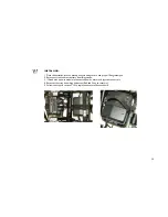
Page 49: ...ve the seat board 3 Disconnect both rear battery box wiring harnesses Red and Grey connectors 4 If fitted with a power module disconnect all power motor and joystick connectors 5 Disconnect front and...

Page 50: ...fting technique 2 Reconnect front and rear battery box fixing straps 3 If fitted with a power module reconnect all power motor and joystick connectors 4 Reconnect battery box wiring harnesses Red and...

Page 51: ...the same time An electrical short may occur and serious personal injury or damage may occur The use of rubber gloves and chemical goggles is recommended when working with batteries NOTE Perform this...

Page 52: ...Disconnect strap and lift battery box lid to expose underlying cables 3 Remove the hex screw and locknut that secures the NEGATIVE black battery cable to the negative battery terminal post 4 Remove th...

Page 53: ...y cables 1 Connect battery cable s to battery s terminal s post s as follows Negative BLACK battery cable to NEGATIVE battery terminal post Positive RED battery cable to POSITIVE battery terminal post...

Page 54: ...ces Handle the battery charger with care if it has been dropped or damaged do not use it Do not use an extension lead for connection from the mains to the charger unless absolutely necessary If you do...

Page 55: ...out delay We strongly advise you however not to wait until this critical point has been reached but to charge the batteries as early and as often as possible after you have used your Powerchair If you...

Page 56: ...o contact your local INVACARE supplier dealer Connect the charger power supply cable to the mains socket and switch the power on The Mains ON and the Charging lights on the charger will come on It is...

Page 57: ...batteries to the collection and recycling location nearest to you Batteries must always be correctly recycled Under no circumstances should batteries be disposed of in domestic refuse NOTE For further...

Page 58: ...the wheels and tyres should be checked periodically for cracks and wear and should be replaced 9 1 Disengaging Engaging Motor Lock Levers WARNING DO NOT engage or disengage motor locks until the power...

Page 59: ...the wheels and tyres should be checked periodically for wear REMOVAL Release and remove the central screw B and the four surrounding screws A using a hex wrench Pull the wheel away from the chair It...

Page 60: ...e in an upwards direction until it engages Repeat for opposite side of chair To De Activate Brake Locate the brake grip handle Push the brake handle in a downward direction until it disengages Repeat...

Page 61: ...d crash test ISO7176 Part 19 was successfully carried out with the chair restrained facing the front of the vehicle It is recommended that these guidelines are followed The powerchairs are not designe...

Page 62: ...he chair must not be used as a seat in transport if a tension adjustable backrest is fitted as this set up will not facilitate the mounting of a headrest Invacare recommend that the lap belt is used i...

Page 63: ...art of the Powerchair accessories etc that can be easily detached should be removed and stored in the vehicle luggage hold during transportation 4 The Powerchair should always be transported in a forw...

Page 64: ...unwin safety com This system comprises of a pair of non adjustable webbing straps with quick release buckles to secure the front Fig 1 of the chair each side A pair of straps complete with D rings lo...

Page 65: ...atteries 5 Follow the steps in section 7 12 to remove the kerb climber 6 Follow the steps in section 7 13 to remove the leg rests 7 To fold the chair take hold of the seat tube and lift Your powerchai...

Page 66: ...2 Adjustments have been made to suit your individual needs and fasteners securely tightened 3 Tyres are in good condition and correctly inflated Or as specified on the tyre side walls CAUTION DO NOT...

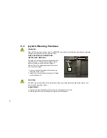
Page 67: ...cording to comfort and arm length as follows There is no height adjustment other than to vary the armrest height 1 Unscrew the small handwheel L located on the underside of the armrest 2 Install remov...

Page 68: ...eat independence and self care Such ability depends largely on the strength of the individual their capabilities and the type of chair No single technique would be practical or possible for all wheelc...

Page 69: ...ble for stabilising the wheelchair and must take precautions to prevent the wheelchair moving or sliding during the transfer i e apply brakes and ensure chair is not in free wheel Be sure that the sea...

Page 70: ...e will scratch the finish Do not store your chair in damp conditions UPHOLSTERY The upholstery on the powerchair is vinyl or Plush cloth material Occasionally wipe with a damp cloth moistened with soa...

Page 71: ...ey are securely attached A visual inspection is usually adequate Ensure locking safety catch operates correctly and secures motor plugs Inspect all wires for worn insulation If any are found they shou...

Page 72: ...OT START Check that the control box is switched on the display will be illuminated and remain stationary Check that both motors are engaged Check that the main controller cable is firmly pushed home D...

Page 73: ...n is placed on this product to encourage you to recycle wherever possible Please be environmentally responsible and recycle this product through your recycling facility at its end of life DISPOSAL The...

Page 74: ...are at your service under the following addresses and telephone numbers European Headquarter Invacare International S rl Route de Cit Ouest 2 CH 1196 Gland Tel 41 0 22 354 60 10 Fax 41 0 22 354 60 11...

Page 75: ...7 00 66 infor aquatec de Ulrich Alber GmbH Vor dem Weissen Stein 21 D 72461 Albstadt Tailfingen Tel 49 0 7432 2006 0 Fax 49 0 7432 2006 299 info ulrich alber de Espa a Invacare SA c Areny s n Pol gon...

Page 76: ...0 318 695 757 Fax 31 0 318 695 758 mobility invacare com care invacare com Norge Invacare AS Grensesvingen 9 Postboks 6230 Etterstad N 0603 Oslo Tel 47 0 22 57 95 00 Fax 47 0 22 57 95 01 norway invaca...

Page 77: ...70 90 info dolomite se Switzerland Mobitec Rehab AG Benkenstrasse 260 CH 4108 Witterswil Tel 41 0 61 487 70 80 Fax 41 0 61 487 70 81 office mobitec rehab ch switzerland invacare com United Kingdom Eir...

Reviews: