Chapter 5 : Diagnostics
15
The DCI function can be enabled and disabled. Additionally, the speed
to which the chair reduces while in Speed Limit can also be set.
OBCs have either normally closed or normally open Inhibit outputs. By
setting the DCI Operation parameter to Normally Open, SHARK will
swap the Normal and Inhibit values in the above table. An open circuit
(>560 ohms) will allow normal drive, while a circuit resistance of 0 will
prevent driving. All other values stay the same. Check the
documentation that came with your OBC for product specifications.
For instance, an OBC that has an open Inhibit contact when the charger
is not plugged in should be set to Normally Open.
3.3 Testing
To ensure that the powerchair meets a minimum level of safety, the following
procedure should be. This procedure should be carried out in a spacious
environment and with due regard to any possible unexpected powerchair
movement in the event of faulty installation.
1.
Raise the wheels off the ground using blocks under the
powerchair frame so that the wheels can turn freely.
2.
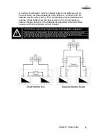
Recheck all wiring, paying particular attention to polarities of
batteries, motors and park brakes.
3.
Make the final connection to the Battery Positive (+) terminal and
close the circuit breakers.
4.
Press the Power button to turn SHARK on. Ensure it turns on
correctly.
5.
Press the Power button again to turn SHARK off. Ensure it turns
off correctly. Press the power button again to turn SHARK back
on.
6.
Ensure the horn is functioning correctly by pressing the Horn
button.
7.
Turn each drive wheel by hand to check that the park brakes are
engaged. The wheels should not move.
8.
Push the joystick slightly out of neutral and listen for the “click” as
the park brakes disengage.
Summary of Contents for Hydra C650PW
Page 29: ...29 ...
Page 34: ...7 7 Electromagnetic Compatibility EMC 48 7 8 Contact Details 49 ...
Page 36: ...GBK80260 Issue 1 1 07 2004 2 THIS PAGE IS LEFT BLANK INTENTIONALLY ...
Page 48: ...GBK80260 Issue 1 1 07 2004 14 THIS PAGE IS LEFT BLANK INTENTIONALLY ...
Page 64: ...GBK80260 Issue 1 1 07 2004 30 THIS PAGE IS LEFT BLANK INTENTIONALLY ...
Page 66: ...GBK80260 Issue 1 1 07 2004 32 THIS PAGE IS LEFT BLANK INTENTIONALLY ...
Page 71: ...Chapter 7 Appendices 37 Dynamic SHARK Looms For DK REMA DK PMA Power Module ...
Page 84: ...Installation Manual DK PMA SHARK Power Module by GBK80262 Issue 1 June 2004 ...
Page 87: ......
Page 89: ...GBK80262 Issue 1 1 07 2004 2 THIS PAGE IS LEFT BLANK INTENTIONALLY ...
Page 91: ...GBK80262 Issue 1 1 07 2004 4 THIS PAGE IS LEFT BLANK INTENTIONALLY ...
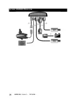
Page 113: ...GBK80262 Issue 1 1 07 2004 26 Dynamic SHARK DK PMA Looms ...
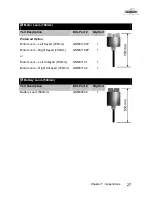
Page 116: ...Chapter 7 Appendices 29 Dynamic SHARK Connector Kits and Adapters ...

