background image


Chapter 2 : The DK-REMA Control Unit 

9

2.5 

Locking SHARK 

Some SHARKs may be supplied factory programmed with a 

Lock

 Feature 

that prevents unauthorized people from turning SHARK on. 


To LOCK SHARK 


While the power is ON, press and hold the 
Power button for 2 seconds. 

The display will turn off immediately. 

After 2 seconds all LED’s will flash briefly and 
the horn will sound a short beep. 

The powerchair will then turn off.  


The Lock feature may be turned on or off. 


To UNLOCK SHARK 


While SHARK is locked, press the Power button 
to turn SHARK on. 

All LED’s will flash briefly. The LED’s will then 
perform a slow right-to-left countdown.  


Press the Horn button twice before the 
countdown is completed (approximately 10 
seconds). 

The current state-of-charge will then be 
displayed and SHARK may be operated 
normally.  


If the user does not press the Horn button twice before the countdown is 
complete, the Horn will sound a short beep and SHARK will turn itself off. 

The unlock sequence must be completed successfully before SHARK will 
drive again normally. 


Summary of Contents for Hydra C650PW

Page 1: ...1 Invacare Australia Pty Ltd ACN 074676378 1 Lenton Place PO Box 5002 North Rocks NSW 2151 Ph 61 2 8839 5333 Fax 61 2 8839 5353 sales invacare com au August 2004 Hydra C650PW Folding Power Wheelchair ...

Page 2: ... DISTRIBUTOR OR DEALER WHERE YOUR ELECTRIC WHEELCHAIR PURCHASED BEFORE ATTENPTING TO USE THIS EQUIPMENT OTHERWISE INJURY OR DAMANGE MAY RESULT Chair User Classification Model Max user Weight Everyday Use Indoor Use Outdoor Use C650PW Folding power wheel chair 100 KGS X X X Back upholstery Armrest Controller Batteries Frame Rear wheel set Legrests Casters fork Motor gear box ...

Page 3: ... 14 Controller Shark Dynamic Controller 15 Drive Train 250W Rear wheel drive with two motors permanent magnet commutator 24V DC motors 16 Weight Capacity 100kg 220 lbs 17 Max Speed 6 5 km h 4 MPH 18 Ground clearance to Batteries 135 mm 5 3 in 19 Ground clearance to Anti tip Wheels 35 mm 1 4 in 20 Turning Radius 965 mm 38 in 21 Climbing Angle 10 22 Range 24 km 15 miles Varies with passenger weight ...

Page 4: ...rward Safety Instructions Unpacking and Assembly Special Features Freewheel levers Armrest Backrest Seat Legrest Wheel lock Safe Driving Techniques Batteries Tyre Pressures Maintenance Cleaning Fault Finding Limited Warranty ...

Page 5: ...e that your power wheelchair is correctly fitted and adjusted by your selling Dealer or by your attending therapist Be sure to engage the wheel locks before entering or leaving the chair The wheel locks are designed to prevent movement of the chair It is preferable to ensure that the front castors are in the forward position before transferring With the castors in the forward position the wheel ba...

Page 6: ... stop when going up an incline special care must be taken to avoid abrupt or sudden forward movement when you resume propelling the chair so as to avoid forces which could tip the chair backwards Always keep the chair under control when going down a ramp or incline Speed should be controlled at all times When a chair is being attended by a carer and a kerb is encountered care should be taken to pr...

Page 7: ...atteries boxes two pieces for 31 AH batteries use one box for a battery 5 Batteries Rechargeable sealed lead acid battery 12V 31 AH and or smaller 6 Battery Tray Steel basket 7 Battery Charger Off board 8 Controller Shark Dynamic Controller 9 Motors 24V DC permanent magnet commutator motors Assembly Please assemble the main parts mentioned as per the following procedure and check the assembly for ...

Page 8: ... for storage or transportation 1 From the rear release the battery box restraining strap Unplug the rear battery box and remove red plugs Unplug the front battery box from the main controller and remove see page 21 for more details 2 Fold up the footplates and unlock the levers that position the legrests Swing the footplates and legrests away Either leave the footplates in this position or remove ...

Page 9: ...d into position connect the power cables to the appropriate plugs and ensure that the power cables are clear of obstacles when replacing the battery box lid Tighten the battery box securing strap 3 Slide the power control module into the mounting bracket under the armrest and secure it into position Your control module can be mounted either on the left or right hand side of the chair Should you wi...

Page 10: ...e chair could roll down on its own causing injury To engage or disengage the freewheel feature 1 Turn the freewheel levers outward to disengage the drive motors see Fig 18 Fig 18 Driver disengaged Fig 19 Drive engaged 2 Turn the free wheel levers inward to engage the drive motors see Fig 19 NOTE It is important to remember that when your C650PW is in freewheel mode the braking system is disengaged...

Page 11: ...osition in order to meet user s demand To adjust turn the screw as Fig 25 shows Backrest The backrest is adjustable by removing the four backrest cane securing screws and selecting the required new height The backrest canes are predrilled as Fig 32 shows Fig 32 WARNING Replace worn or torn fabric immediately Failure to do so may result in a fall and severe injury to you ...

Page 12: ...inch strip and adjust the hook and pile to increase the upholstery tension 3 Replace the pinch strip and using a punch or a similar tool insert the tip through the pinch strip and into a centre rivnut 4 Lever the upholstery into position and secure a locating screw If abnormal pressure is required to align the locating screws then remove the upholstery and readjust the hook and pile 5 Repeat this ...

Page 13: ...ension tube and foot plate up or down to the desired height Retighten the securing hardware as Fig 36 shows Fig 36 Swing away and detachable legrest with extension tube OPTIONS There is elevating legrest as an option WARNING Never lift the wheelchair by the legrests These parts are detachable and will not bear the weight of this chair Lift this chair ONLY by non detachable parts of the main frame ...

Page 14: ...8 shows Fig 38 To release wheel lock Fig 39 To apply wheel lock 3 DO NOT use the wheel locks to slow the wheelchair whilst descending an incline 4 Wheel locks can be adjusted as tyre wear increases To adjust loosen the frame mounting clamp and slide the wheel lock upward Retighten the clamp while wheel lock engages to correct position Your selling dealer can assist with adjustment Please note When...

Page 15: ...ir to SLOW as described in the CONTROLLER CONTROL UNIT OWNER S MANUAL following this manual 2 Release the wheel locks 3 Press the on off switch 4 Allow two seconds to elapse before engaging the joystick This is a safety feature to prevent sudden starts 5 Push the joystick gently forward applying a steady even pressure The further you push the joystick the faster the chair will go The chair will st...

Page 16: ...stacles en counted when driving If operating your chair on the roads please check with your local Police Department regarding necessary identification and safety devices such as reflectors Chair Operation on surfaces that require Special Care When driving up or down ramps it is recommended that the user 1 Visually checks to see if the angle of the slope is less than 15 degrees 2 Checks to see that...

Page 17: ... chair up the kerb If the kerb height is greater than 35mm it is not recommended that the user climb or descend the kerb Should there be any doubt then an assistant should be called to supervise the operation Steep Slopes When the power wheelchair is to be operated up and down steep slopes it is recommended that the user 1 Visually checks to see if the angle of the slope is less than 15 degrees 2 ...

Page 18: ...ing the Batteries 1 Batteries should be charged every night in a well ventilated room 2 DO NOT place the power wheelchair near radiators or open fireplaces whilst charging 3 DO NOT smoke or permit naked flames in the immediate vercinity 4 Turn the chair controller power off before charging 5 It is advisable that the batteries be charged for a minimum of 10 hours per night to ensure a full return t...

Page 19: ...f the maximum charge level the on off lamp on the controller will flash This indicates that whilst you have some reserve power the batteries should be recharged Note 1 Do not use batteries other than the recommended type for your chair and never use a charger other than the one supplied for the purpose 2 If the chair is not used for a long period of time e g school holidays hospitalisation or when...

Page 20: ...INVACARE Wire diagram Date August 20 2004 C650PW EA power chair with Shark controller Connector Red Black White Red Red Cut out switch Cut out switch Red White Red Controller Lead Black Front ...

Page 21: ...s noting the polarity of the lugs Remove the wiring loom 8 Repeat step 6 for the other battery 9 Inspect the terminals on the wiring loom and the lugs on the replacement batteries to make sure they are clean If they are not clean with a warm solution of bicarbonate of soda one dessert spoon and water approxi mately five litres It is important that you wash your hands afterwards 10 Connect the term...

Page 22: ...rd equipment OPTION 12 1 2 x 2 1 4 airless tyres WARNING Make sure the tyre is completely deflated before attempting repair Follow these easy steps for a quick and safe repair 1 Completely deflate the tyre if pneumatic 2 Use an ratchet and socket to remove the drive wheel screw from the centre hub of the wheel See Fig 41 3 Pull the wheel off of the axle 4 Separate the tyre and tube from the rim 5 ...

Page 23: ...re your power chair is functioning properly and helps prevent future complications This should include 1 Checking the tyres and tubes 2 Checking the batteries and terminals 3 Checking the controller programme for the user s needs 4 Checking the wheelchair frame 5 Checking the upholstery condition Regular Maintenance and Cleaning 1 Avoid knocking or bumping the controller especially the joystick 2 ...

Page 24: ...ase it Check the rubber boot around the base of the joystick for damage Visually inspect the boot Do not handle or try to repair it See authorized dealer if there is any problem 13 Visually inspect the controller harnesses Make sure that they are not frayed or cut or have any wires exposed See authorized dealers if there is a problem with any of these harnesses 14 Ensure that all parts of the cont...

Page 25: ...he leads have been properly connected and the mains power is turned on If this doesn t cause the red light on the charger to illuminate turn the mains power off disconnect the lead from the mains to the battery charger Contact your Dealer and advise of the problem Problem The chair is difficult to steer Action First check the tyre pressure of all the tyres Second check to see if both the clutches ...

Page 26: ...ot replacing the motor brushes after heavy wear to the brushes Motor brushes are wear items and are not warranted The chair side frames are guaranteed for a period of FIVE YEARS from date of purchase Warranty exclusions Batteries Tyres and tubes Upholstery and seating Repairs and or modifications made to any part without specific prior Written consent from Invacare Australia Pty Ltd Circumstances ...

Page 27: ...ciated with the freight of the chair or any faulty components are the responsibility of the owner 5 Labor charge incurred in the installation or repair of the above mentioned parts plus all freight charges are not included in the warranty 6 Any parts found to be defective due to faulty workmanship and or materials will be renewed or repaired at the Company s discretion without charge to the owner ...

Page 28: ...E The information and specification of C650PW contained in this User s Manual is subject to change without prior notice No part of this document may be photocopied reproduced transmitted transcribed stored in a retrieval system or translated to another language or computer language in any form or by any means electronic mechanical magnetic optical chemical manual or otherwise without prior written...

Page 29: ...29 ...

Page 30: ...ion including pricing and specifications subject to change without prior notice Photographs are for illustration purposes only may vary from product depiction Invacare and Yes you can are trademarks of Invacare Corporation 2001 Invacare Corporation Invacare Australia 1 Lenton Place North Rocks NSW 2151 Australia Phone 02 8839 5333 Fax 02 8839 5353 ...

Page 31: ...Installation Manual SHARK DK REMA Series of Control Units 2 Button Remote by GBK80260 Issue 1 June 2004 ...

Page 32: ...e repair of any SHARK component Do not install maintain or operate this equipment without reading understanding and following this manual including the Safety and Misuse Warnings otherwise injury or damage may result Due to continuous product improvement Dynamic reserves the right to update this manual This manual supersedes all previous issues which must no longer be used Dynamic reserves the rig...

Page 33: ...rchair Manufacturer 15 4 1 3 Programming by the Dealer 16 4 2 Powerchair Manufacturer Programming in Detail 17 4 2 1 Chair Set Up 18 4 2 2 Drive Program 19 4 3 Chair Tamer 21 4 3 1 Stability Profiles 21 4 3 2 Stability Profiles 1 4 21 4 3 3 Stability Profiles 5 8 22 4 3 4 Stability Profile Parameters 23 4 3 5 Drive Program Swap Feature 24 4 4 Dealer Programming in Detail 25 5 Diagnostics 27 5 1 In...

Page 34: ...7 7 Electromagnetic Compatibility EMC 48 7 8 Contact Details 49 ...

Page 35: ...air performance control and safety A number of control units are available to meet a wide range of user needs These range from optimally small highly ergonomic units to units with a more traditional appearance and standard functionality A choice of power modules offers basic drive only functionality up through sophisticated modules supporting multiple seat adjustments lights etc No heavy power cab...

Page 36: ...GBK80260 Issue 1 1 07 2004 2 THIS PAGE IS LEFT BLANK INTENTIONALLY ...

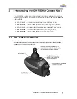
Page 37: ...cable lengths DK REMA01 1 5 meter Gunmetal Gray Case Light Gray Accent DK REMA02 1 meter cable Gunmetal Gray Case Light Gray Accent DK REMA03 0 5 meter cable Gunmetal Gray Case Light Gray Accent DK REMA05 1 5 meter cable Black Case Dark Gray Accent DK REMA06 1 meter cable Black Case Dark Gray Accent 2 1 The DK REMA Control Unit All user controls can be accessed from the simple ergonomically design...

Page 38: ...tes well charged batteries o If only amber and red LED s are lit the batteries are moderately charged Recharge before undertaking a long trip o If only red LED s are lit the batteries are running out of charge Recharge as soon as possible SHARK Lock Mode countdown Program inhibit or charge modes Fault indication Flash Codes The following table indicates what the gauge will display for any given st...

Page 39: ...SHARK is in programming inhibit and or charging mode The steady LED s indicate the current state of battery charge Right GREEN LED is flashing SHARK is in SPEED LIMIT mode The current state of battery charge will be displayed at the same time All LED s flashing slowly SHARK has detected an Out Of Neutral At Power Up OONAPU condition Release the joystick back to neutral All LED s flashing quickly S...

Page 40: ...ppear OONAPU Out Of Neutral At Power Up is a feature that prevents SHARK from driving if the joystick is out of neutral when SHARK is either turned on or an inhibit condition removed This feature prevents sudden and unexpected powerchair movements Turning the Power OFF Press the Power button The LED s will turn off Alternatively SHARK may be placed into a Lock Mode This may be preferable to turnin...

Page 41: ...button or displacing the joystick will bring the system out of Sleep mode When Wakeup style has been set to Buttons Only pressing the On Off button ONLY will bring the system out of Sleep mode The Sleep feature may be turned on or off the method for bringing the system out of Sleep Mode can be changed and the amount of time before Sleep mode is entered can be modified SHARK may enter Sleep Mode wh...

Page 42: ... of their powerchair to suit their preference or environment by turning the speed control dial Simply turn the dial fully clockwise to travel at top speed when the joystick is pushed fully forward The top speed progressively reduces as the dial is turned counter clockwise Powerchair driving performance speed acceleration etc can be further customized to suit the needs and preferences of each user ...

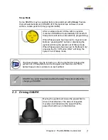
Page 43: ...The Lock feature may be turned on or off To UNLOCK SHARK While SHARK is locked press the Power button to turn SHARK on All LED s will flash briefly The LED s will then perform a slow right to left countdown Press the Horn button twice before the countdown is completed approximately 10 seconds The current state of charge will then be displayed and SHARK may be operated normally If the user does not...

Page 44: ... is being charged by cycling between a left to right chase and displaying the current battery state of charge Driving is prevented inhibited while the system is being charged Once the Battery Charger displays a full battery charge the battery charger plug may be removed If SHARK is turned off or goes into sleep while charging charging will continue Although the SHARK Information Gauge will display...

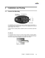
Page 45: ...M5 screws These should be tightened to a torque of approximately 2 Nm 18 lbf in There are three mounting options available plate mount and left or right tube mount Plate Mount The SHARK Control Unit can be mounted using a flat plate typically welded to a tubular arm The mounting area on the Control Unit has support through the center along with lips to support the outside of the bracket ...

Page 46: ...elect a screw length that protrudes between 4mm and 6mm into the case Do not over tighten the mounting screws These should be tightened to a torque of 2 Nm 18 lbf in 3 1 1 SHARK Communications Bus The SHARK Power Module communicates to the Control Unit through the SHARK Communications Bus The Bus also supplies power to the Control Unit The connector is keyed and can only be plugged in one way the ...

Page 47: ...ton again to turn SHARK off Ensure it turns off correctly Press the power button again to turn SHARK back on 6 Ensure the horn is functioning correctly by pressing the Horn button 7 Turn each drive wheel by hand to check that the park brakes are engaged The wheels should not move 8 Push the joystick slightly out of neutral and listen for the click as the park brakes disengage 9 Move the joystick i...

Page 48: ...GBK80260 Issue 1 1 07 2004 14 THIS PAGE IS LEFT BLANK INTENTIONALLY ...

Page 49: ... and users All programmed values are stored in the Power Module In the event that the Control Unit is replaced there is no need to reprogram SHARK If the Power Module is replaced SHARK can simply be reprogrammed with an identical powerchair program SHARK can be programmed at three points 4 1 1 Programming by Dynamic Dynamic supplies SHARK pre configured with a sensible generic program Customizatio...

Page 50: ...ng by the Dealer The primary task of the dealer is to select the most appropriate of the three Drive Programs and tune it so that it meets the specific needs and preferences of the powerchair user For instance the powerchair manufacturer may provide front mid and rear wheel Drive Programs for any single chair type The dealer then selects the Drive Program that includes all the technical functional...

Page 51: ... in Detail The powerchair program is made up of subgroups each of which defines a separate aspect of the chair A description of each group and parameter is provided for your reference although some groups or parameters may not be viewable or editable at your access level ...

Page 52: ...drive with the joystick full left or right and the speed dial fully counter clockwise Sleep Timer Set the amount of time in minutes that SHARK will turn itself off after no user input Set to 0 to disable this feature Wakeup Style Defines how a user can wake SHARK out of Sleep mode Select Button or Joystick Button Joystick Throw Defines the amount of joystick movement required for full speed Option...

Page 53: ...ll be displayed by the Hand Held Programmer Maximum Forward Speed The maximum speed SHARK will drive with the joystick full forward and the speed pot fully clockwise Forward Acceleration Sets how quickly SHARK will accelerate when the joystick is moved forward from neutral Forward Deceleration Sets how quickly SHARK will decelerate when the joystick is moved toward neutral from a forward position ...

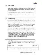
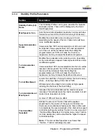
Page 54: ... Particularly useful for reducing drive sensitivity to hand tremors Stability Profile The basis of Chair Tamer select one of the eight pre defined stability profiles to define the application of Chair Tamer Traction Defines the amount of assistance SHARK provides in controlling the chair when a Stability Profile with Chair Tamer is selected effectively amplifying the effect of the Stability Profil...

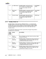
Page 55: ...simply by selecting the appropriate Active Stability Profile within each Drive Program For example if Drive Program 2 has been set up with Active Stability Profile 7 selected then the chair will behave with the speed and response characteristics defined by Drive Program 2 but overlaid with a level of Chair Tamer or drive assistance as specified by Stability Profile 7 The 8 Stability Profiles are g...

Page 56: ...airs that can be converted between Front Wheel Drive FWD and Rear Wheel Drive RWD by swivelling the seat This is often referred to as a Swivel function For best results with this style of chair use the Drive Program Swap feature described in the next section Chair Tamer Profile Name Description 5 No CT Swivelled Does not apply any Chair Tamer to the chair Motor Polarity is reversed 6 Lo CT Swivell...

Page 57: ...nto the turn will be lessened Values greater than 100 and acceleration into the turn will be increased Note that setting this programmable over 100 will make the chair more responsive but may increase the likelihood of spinout Turn at Max Speed Lowers the sensitivity of turning the faster the chair is being driven reducing snaking if the chair is FWD Will also reduce the ability to turn quickly at...

Page 58: ...ction the seat is facing If the Active Drive Program parameter is set to any of Drive Program 1 Drive Program 2 or Drive Program 3 applying the Swivel function on the Drive Control Input DCI will achieve item 1 only If the Active Drive Program parameter is set to DCI Select 1 2 applying the Swivel function on the DCI will achieve both items 1 and 2 1 When the DCI is Normal the active Drive Program...

Page 59: ...EDIT START PROGRAM Joystick Throw JJJJJJJJJJJ EXIT NEXT SWAP Swaps Normal Short Very Short PROGRAM Sleep Timer SS Minutes EXIT NEXT UP DOWN PROGRAM Veer Correction VVVVVVV EXIT NEXT LEFT RIGHT T MENU General Shaded screens are only accessed once technician mode is entered otherwise they are skipped Technician mode is exited whenever the programmer is unplugged or power is cycled Key WWWWWW System ...

Page 60: ...PPPPPP Reverse Acceleration xx EXIT NEXT UP DOWN PPPPPPPPPPP Reverse Deceleration xx EXIT NEXT UP DOWN PPPPPPPPPPP Max Turn Speed xx EXIT NEXT UP DOWN PPPPPPPPPPP Turn Acceleration xx EXIT NEXT UP DOWN PPPPPPPPPPP Turn Decleration xx EXIT NEXT UP DOWN PPPPPPPPPPP Tremor Damping xx EXIT NEXT UP DOWN PPPPPPPPPPP Traction xx EXIT NEXT UP DOWN MENU PPPPPPPPPP Load compensation Xx mOhms EXIT NEXT UP DO...

Page 61: ... allowing it to return to the neutral position the fault will immediately clear If the condition persists after removing your hand the joystick may be damaged Consult a service agent The nature of the abnormal condition is indicated by a flash code This is a sequence of flashes separated by a pause followed by a repetition of the sequence The number of flashes relates to the condition For instance...

Page 62: ...vide more specific diagnostics information that is suitable for repair technicians In some cases viewing a history of any abnormal conditions that occurred previously on the system may be useful in diagnosing the current condition This can be done by entering the Fault Log from the Diagnostics menu Usage statistics are also available from this menu DYNAMIC Wizard Wizard is the preferred diagnostic...

Page 63: ...t Motor Fault Check the right motor connections and cabling 5 Left Park Brake Fault Check the left park brake connections and cabling 6 Right Park Brake Fault Check the right park brake connections and cabling 7 SHARK Control Unit Fault Check the SHARK Communications Bus connections and wiring Replace the Control Unit 8 SHARK Power Module Fault Check SHARK connections and wiring Replace the Power ...

Page 64: ...GBK80260 Issue 1 1 07 2004 30 THIS PAGE IS LEFT BLANK INTENTIONALLY ...

Page 65: ...l Plastic Finish Protection Rating IPx4 Shipping Weight 460g Force required to operate joystick 800 grams Min Nominal Max Units Operating Temperature Range 25 50 C Operating Temperature Range SHARK Programming Adapter 0 50 C Storage Temperature Range 40 65 C Operating Humidity Range 0 90 RH ...

Page 66: ...GBK80260 Issue 1 1 07 2004 32 THIS PAGE IS LEFT BLANK INTENTIONALLY ...

Page 67: ... Chair Set Up Lowest Forward Speed 5 100 ü ü ü Lowest Turn Speed 5 100 ü ü ü Sleep Timer Off 30 Min ü ü ü ü Wakeup Style Button Joystick or Button ü Joystick Throw Normal Short Very Short ü ü ü ü Lock Enable No Yes ü ü ü Field Programmability Limited Full ü Active Drive Program 1 3 DCI Select 1 2 If set to DCI Select 1 2 it can not be edited with the HHP T ü ü ü Emergency Deceleration 50 100 ü ...

Page 68: ...c ü Veer Compensation 10 10 ü ü ü ü Drive Programs Drive Program Name 15 character description O O ü Maximum Forward Speed 30 100 ü ü ü ü Forward Acceleration 20 90 ü ü ü ü Forward Deceleration 30 100 ü ü ü ü Maximum Reverse Speed 30 100 ü ü ü ü Reverse Acceleration 20 90 ü ü ü ü Reverse Deceleration 30 100 ü ü ü ü Maximum Turn Speed 10 90 ü ü ü ü Turn Acceleration 10 90 ü ü ü ü Turn Deceleration ...

Page 69: ...0 ü ü ü ü Stability Profiles Stability Profile Name 15 character description ü Max Speed in Turn 5 100 ü Speed Acceleration Scalar 0 200 ü Turn Acceleration Scalar 0 200 ü Turn at Max Speed 5 100 ü Turn Acceleration at Max Speed 100 300 ü Traction at Max Speedpot 0 50 ü FWD RWD Swivel No Yes ü ü Editable at this level O Viewable at this level T Editable by HHP in Technician Mode only ...

Page 70: ...anual GBK80260 1 Dynamic SHARK DK REMB 3 Button Remote Installation Manual GBK80261 1 Dynamic SHARK Programming Accessories Part Description DCL Part Qty Unit Dynamic SHARK Programming Adapter DK ADAPT 1 Wizard 5 Kit Programming Kit Contains software cables and adapter no dongle DWIZ5 KIT 1 Wizard 5 Software Only CD DWIZ5 SW 1 Wizard Dongle OEM or Dealer version Parallel Port DWD OEM or DWD DLR 1 ...

Page 71: ...Chapter 7 Appendices 37 Dynamic SHARK Looms For DK REMA DK PMA Power Module ...

Page 72: ...ty Unit Preferred Option Motor Loom Left Keyed 700mm GSM61191P 1 Motor Loom Right Keyed 700mm GSM61192P 1 or Motor Loom Left Unkeyed 700mm GSM61191 1 Motor Loom Right Unkeyed 700mm GSM61192 1 Ë Battery Loom 500mm Part Description DCL Part Qty Unit Battery Loom 500mm GSM80204 1 ...

Page 73: ...MA Power Module Part Description DCL Part Qty Unit DCI Loom 300mm GSM80205 1 Î SHARK Control Unit Extension Cable Part Description DCL Part Qty Unit SHARK Control Unit Extension Cable 1200mm GSM80232 1 SHARK Control Unit Extension Cable 900mm GSM80231 1 SHARK Control Unit Extension Cable 640mm GSM80211 1 SHARK Control Unit Extension Cable 300mm GSM80203 1 ...

Page 74: ...GBK80260 Issue 1 1 07 2004 40 Dynamic SHARK Connector Kits and Adapters DK PMA Power Module Shown ...

Page 75: ... Housing Unkeyed GCN0790 2 Or Fb Left Motor Connector Housing Keyed GCN60146 1 Fc Right Motor Connector Housing Keyed pictured GCN60147 1 Ð Single Motor Connector Kit Unkeyed GSM60182 or Keyed Left GSM60182PL or Keyed Right GSM60182PR Item Part Description DCL Part Qty Unit A Innergy Contact Female GCN0781 2 B Positronic Contact Female GCN0794 2 C Connector Boot not shown GCN0787 1 Either Da Motor...

Page 76: ... DK PMA Power Module GSM80206 Item Part Description DCL Part Qty Unit A DCI Connector Housing AMP MateNlok Mini 4w Hse 172167 1 GCN8001 1 B DCI Pins 26 22 AWG GCN0687 4 Ó Beau Chair to SHARK Controller Adapter 300mm Part Description DCL Part Qty Unit Beau Chair to SHARK Controller Adapter Loom 300mm GSM80202 1 DX Batteries to SHARK Controller Adapter Loom 175mm Part Description DCL Part Qty Unit D...

Page 77: ...ce with the device classification the SHARK wheelchair controller is designed to comply with the requirements of the European Medical Device Directive 93 42 EEC and 21 CFR 820 30 The SHARK Controller has been designed such that the combination of the wheelchair and the SHARK Controller along with accessories as applicable complies with the requirements of the MDD Harmonized standards EN12184 and E...

Page 78: ...All Dynamic electronic components should be kept free of dust dirt and liquids If necessary wipe with a cloth dampened with warm water Do not use solvents or abrasive cleaners 4 There are no user serviceable parts in any Dynamic electronic component Do not attempt to open any case or undertake any repairs or warranty claims will be affected 5 Where any doubt exists consult your nearest service cen...

Page 79: ...ent has been thoroughly checked upon completion of installation and all programmable options correctly adjusted for safe operation prior to use has been correctly installed has been used solely in accordance with this manual has been properly connected to a suitable power supply in accordance with this manual has not been subjected to misuse or accident or been modified or repaired by any person o...

Page 80: ...adjustments should only be made indoors or outdoors in dry conditions The user should turn the system off before getting in and out of the vehicle Do not operate the vehicle if it behaves erratically or shows abnormal response heating smoke or arcing Turn the system off at once and consult your service agent If the vehicle drives without demand press the Power button Ensure that the battery charge...

Page 81: ...ces In the event of the fault indicator flashing while driving the operator must ensure that the system is behaving normally If not the system must be turned off and a service agent contacted Report any malfunctions immediately to your service agent Service and Configuration Warnings The following warnings are applicable to the installation technician only After the vehicle has been configured che...

Page 82: ... Emissions Motors Motor brushes generate electromagnetic emissions It may be necessary to fit capacitors between the brush holders and motor case Ensure the leads are kept as short as possible A suitable capacitor is 4n7 250V Polypropylene Wiring Keep wire lengths as short as practical for a tidy layout Minimize any wire loops particularly loops of single wires as opposed to wire pairs Endeavor to...

Page 83: ...ion including pricing and specifications subject to change without prior notice Photographs are for illustration purposes only may vary from product depiction Invacare and Yes you can are trademarks of Invacare Corporation 2001 Invacare Corporation Invacare Australia 1 Lenton Place North Rocks NSW 2151 Australia Phone 02 8839 5333 Fax 02 8839 5353 ...

Page 84: ...Installation Manual DK PMA SHARK Power Module by GBK80262 Issue 1 June 2004 ...

Page 85: ...e repair of any SHARK component Do not install maintain or operate this equipment without reading understanding and following this manual including the Safety and Misuse Warnings otherwise injury or damage may result Due to continuous product improvement Dynamic reserves the right to update this manual This manual supersedes all previous issues which must no longer be used Dynamic reserves the rig...

Page 86: ... Connections 13 3 3 Testing 15 4 Programming the DK PMA 17 4 1 Introduction 17 4 2 DK PMA Programmable Parameter Descriptions 17 5 Diagnostics 19 5 1 Introduction 19 5 2 Diagnostics Tools 20 6 Specifications 21 6 1 Electrical Specifications 21 6 2 Physical Specifications 22 7 Appendices 23 7 1 Programmable Parameters details 23 7 2 Accessories Parts List 25 7 3 Intended Use and Regulatory Statemen...

Page 87: ......

Page 88: ...ance control and safety A number of control units are available to meet a wide range of user needs These range from optimally small highly ergonomic units to units with a more traditional appearance and standard functionality A choice of power modules is also available offering basic drive only functionality up through sophisticated modules supporting multiple seat adjustments lights etc No heavy ...

Page 89: ...GBK80262 Issue 1 1 07 2004 2 THIS PAGE IS LEFT BLANK INTENTIONALLY ...

Page 90: ...mance DCI connector that enables Shark to control seat swivel stop and slow down features Direct On Board Battery Charger connection The physical differences between the SHARK Family Power Modules are described below A 4 Pin DCI connector is featured on DK PMA 60 Amp Drive Only Power Module DK PMB 01 60 Amp Drive Only 15 Amp Boost A 12 Pin SHARK Port is featured on DK PMB 11 60 Amp Power Module 15...

Page 91: ...GBK80262 Issue 1 1 07 2004 4 THIS PAGE IS LEFT BLANK INTENTIONALLY ...

Page 92: ...teries and motor is recommended to reduce the length of high current wires Use both screw positions to attach the SHARK Power Module M4 11 64 x 30mm socket cap screws are recommended Select a screw length that protrudes between 4mm and 6mm into the case Do not over tighten the mounting screws These should be tightened to a torque of 2 Nm 2 7 lb ft Regardless of mounting orientation protect powerch...

Page 93: ...nt voltage loss at high current 3 The type of cable used must be appropriate for the mechanical and environmental abuse it is likely to encounter 4 Heavy gauge wire is mandatory for high current connections batteries and motors For lower current wiring a gauge heavier than required to meet the current carrying requirements is recommended for mechanical robustness Generally speaking wire gauges sma...

Page 94: ...ld be kept as short as possible To minimise EMC generating loops pairs of wires should be run together where possible e g run Motor Positive and Motor Negative leads together Avoid running wires in close proximity to the motors 3 2 2 Typical Cabling Installation ...

Page 95: ...ection 4 Battery Negative 3 2 3 Battery Connections The Battery connector has two terminals Battery Positive and Battery Negative For a 60 Amp controller the recommended MINIMUM battery wire size is 6 mm2 for runs of up to 800 mm increasing by 1 0 mm2 for each additional 400 mm run length The heavier the wire the better chair performance will be The final connection to the Battery Positive termina...

Page 96: ...ether single battery box the best position for the circuit breaker is between the two batteries If the batteries are separated individual battery boxes each battery requires a circuit breaker A 30 40 Amp slow acting thermal type circuit breaker is suggested The thermal circuit breaker should have a trip rating no higher than the current limit of the Power Module Check thoroughly to ensure that it ...

Page 97: ...3 mm2 for runs of up to 400 mm increasing by 0 5 mm2 for each additional 200 mm run length The heavier the wire the better chair performance will be 3 The length and gauge of wire effects the wire resistance and hence the optimum Load Compensation setting Ensure the Load Compensation parameter is tuned to match the chair wiring 4 Left and right motors must not be physically interchangeable The pre...

Page 98: ... must be set to DUAL 24 Volt Park Brake Wiring Single Alternatively two 24V park brakes can be wired in parallel from the M2 connector as below For this purpose the M2 connector must be used If the Park Brakes are connected to the M1 connector instead of M2 a Left Park Brake fault Flash Code 5 will occur For this configuration the Park Brake setting must be set to Single If set to DUAL a Right Par...

Page 99: ...his configuration the Park Brake setting must be set to Single If set to DUAL a Right Park Brake fault Flash Code 6 will occur 3 2 5 SHARK Communications Bus The SHARK Power Module communicates to the Control Unit through the SHARK Communications Bus The Bus also supplies power to the Control Unit The connector is keyed and can only be plugged in one way the Control Unit symbol on top of the plug ...

Page 100: ...g too fast may be dangerous The value to which it slows down is programmable Swivel Automatically swaps the drive motor polarities when the powerchair swaps or swivels between front and rear wheel drive When the Active Drive Program is set to DCI Input 1 2 Swivel will change into a Drive Program Swap mode and will automatically swap from Drive Program 1 to Drive Program 2 whenever the DCI Swivel i...

Page 101: ...80 When the seat is swiveled 1 SHARK will automatically change to Drive Program 2 which contains drive settings and a Stability Profile optimized for FWD 2 SHARK will limit speed to 80 When the OBC is plugged into a power socket an inhibit switch internal to the OBC will close 0 resistance inhibiting drive DCI Operation Normally Closed DCI Operation Normally Open DCI Speed Limit 60 DCI Speed Limit...

Page 102: ...g procedure should be This procedure should be carried out in a spacious environment and with due regard to any possible unexpected powerchair movement in the event of faulty installation 1 Raise the wheels off the ground using blocks under the powerchair frame so that the wheels can turn freely 2 Recheck all wiring paying particular attention to polarities of batteries motors and park brakes 3 Ma...

Page 103: ...the park brakes re engaging 11 Turn off SHARK and remove the blocks from under the powerchair 12 Turn SHARK back on and turn the speed dial to the lowest speed setting fully counter clockwise 13 Sit in the powerchair and drive in all directions slowly checking for precise and smooth control 14 Repeat at higher speeds 15 Drive the wheelchair on a 1 6 ramp and check for normal power smoothness and p...

Page 104: ...performance for a wide variety of powerchair configurations and users All programmed values are stored in the Power Module In the event that the Control Unit is replaced there is no need to reprogram SHARK If the Power Module is replaced SHARK can simply be reprogrammed with an identical powerchair program 4 2 DK PMA Programmable Parameter Descriptions Setting Description Active Drive Program Defi...

Page 105: ...ick directly forward will drive in a straight line Motor Swap When set to Yes the motors M1 and M2 will be swapped Left Motor Invert Reverses the polarity of the left motor M1 For example a forward command will cause the motor to turn in the reverse direction Right Motor Invert Reverse the polarity of the right motor M2 For example a forward command will cause the motor to turn in the reverse dire...

Page 106: ...oystick and allowing it to return to the neutral position the fault will immediately clear If the condition persists after removing your hand the joystick may be damaged Consult a service agent Flash Description 1 User Fault Possible stall timeout or user error 2 Battery Fault Check the batteries cabling 3 Left Motor Fault Check the left motor connections cabling 4 Right Motor Fault Check the righ...

Page 107: ...igit code will be displayed which indicates the condition The first two digits provide the flash code number The second two digits provide more specific diagnostics information that is suitable for repair technicians DYNAMIC Wizard Wizard is the preferred diagnostics tool in the workshop environment providing a full fault history and verbal descriptions of each flash and associated servicing code ...

Page 108: ...with SHARK DX HHP and SHARK Support Tool Min Nominal Max Units SHARK Operating Voltage Vbatt 18 24 32 Volts Reverse Supply Voltage 32 Volts Current Rating Peak 60 secs 20 C initial 55 60 63 Amps Continuous 20 C ambient 13 15 Amps SHARK Park Brake Output Voltage Vbatt 1 2 Vbatt Volts Current 0 6 0 7 Amps Quiescent Current idle 120 150 mAmps Drive Control Input Output Current 8 15 mAmps Working Inpu...

Page 109: ...ie cast Aluminum Finish Powder coated Rolling Thunder Charcoal Silver Protection Rating IPx4 Shipping Weight 960g Min Nominal Max Units Operating Temperature Range 25 50 C Operating Temperature Range SHARK Programming Adapter 0 50 C Storage Temperature Range 40 65 C Operating Humidity Range 0 90 RH ...

Page 110: ... Dealer SHARK Support Tool OEM Chair Set Up Field Programmability Limited Full Active Drive Program 1 3 DCI Select 1 2 If set to DCI Select 1 2 it can not be edited with the HHP T DCI Operation Off Normally Open Normally Closed DCI Speed Limit 0 100 Emergency Deceleration 50 100 Parkbrake Type Single Dual O O Software Current Limit 10 60 Amps Stall Timeout 0 60 Sec ...

Page 111: ...ler SHARK Support Tool OEM Veer Compensation 10 10 Motor Swap No Yes Left Motor Invert No Yes Right Motor Invert No Yes Drive Programs Load Compensation 0 1000 limited to Maximum Load Compensation mΩ T Maximum Load Compensation 0 1000 mΩ Editable at this level O Viewable at this level T Editable by HHP in Technician Mode only ...

Page 112: ...al GBK80260 1 Dynamic SHARK DK REMB 3 Button Remote Installation Manual GBK80261 1 Dynamic SHARK Programming Accessories Part Description DCL Part Qty Unit Dynamic SHARK Programming Adapter DK ADAPT 1 Wizard 5 Kit Programming Kit Contains software cables and adapter no dongle DWIZ5 KIT 1 Wizard 5 Software Only CD DWIZ5 SW 1 Wizard Dongle OEM or Dealer version Parallel Port DWD OEM or DWD DLR 1 Wiz...

Page 113: ...GBK80262 Issue 1 1 07 2004 26 Dynamic SHARK DK PMA Looms ...

Page 114: ...Unit Preferred Option Motor Loom Left Keyed 700mm GSM61191P 1 Motor Loom Right Keyed 700mm GSM61192P 1 or Motor Loom Left Unkeyed 700mm GSM61191 1 Motor Loom Right Unkeyed 700mm GSM61192 1 Battery Loom 500mm Part Description DCL Part Qty Unit Battery Loom 500mm GSM80204 1 ...

Page 115: ...300mm Part Description DCL Part Qty Unit DCI Loom 300mm GSM80205 1 SHARK Control Unit Extension Cable Part Description DCL Part Qty Unit SHARK Control Unit Extension Cable 1200mm GSM80232 1 SHARK Control Unit Extension Cable 900mm GSM80231 1 SHARK Control Unit Extension Cable 640mm GSM80211 1 SHARK Control Unit Extension Cable 300mm GSM80203 1 ...

Page 116: ...Chapter 7 Appendices 29 Dynamic SHARK Connector Kits and Adapters ...

Page 117: ...tor Housing Unkeyed GCN0790 2 Or Fb Left Motor Connector Housing Keyed GCN60146 1 Fc Right Motor Connector Housing Keyed pictured GCN60147 1 Single Motor Connector Kit Unkeyed GSM60182 or Keyed Left GSM60182PL or Keyed Right GSM60182PR Item Part Description DCL Part Qty Unit A Innergy Contact Female GCN0781 2 B Positronic Contact Female GCN0794 2 C Connector Boot not shown GCN0787 1 Either Da Moto...

Page 118: ...ive Control Input DCI Connector Kit GSM80206 Item Part Description DCL Part Qty Unit A DCI Connector Housing AMP MateNlok Mini 4w Hse 172167 1 GCN8001 1 B DCI Pins 26 22 AWG GCN0687 4 Beau Chair to SHARK Controller Adapter 300mm Part Description DCL Part Qty Unit Beau Chair to SHARK Controller Adapter Loom 300mm GSM80202 1 DX Batteries to SHARK Controller Adapter Loom 175mm Part Description DCL Pa...

Page 119: ...s a component of a Class I medical device as detailed in the Council Directive 93 42 EEC concerning Medical Devices USA The SHARK Controller is a component of a Class II medical device Powered Wheelchair as detailed in 21 CFR 890 3860 Compliance and Conformance with Standards In accordance with the device classification the SHARK wheelchair controller is designed to comply with the requirements of...

Page 120: ...d Held Programmer and the SHARK Support Tool The adapter is not intended to alter the controller in any way but simply passes information to and from the controller The information passed may alter the controller performance The intended power source is a 24V battery supply from the Shark controller The intended environment is indoors or outdoors in dry conditions ...

Page 121: ...All Dynamic electronic components should be kept free of dust dirt and liquids If necessary wipe with a cloth dampened with warm water Do not use solvents or abrasive cleaners 4 There are no user serviceable parts in any Dynamic electronic component Do not attempt to open any case or undertake any repairs or warranty claims will be affected 5 Where any doubt exists consult your nearest service cen...

Page 122: ...ent has been thoroughly checked upon completion of installation and all programmable options correctly adjusted for safe operation prior to use has been correctly installed has been used solely in accordance with this manual has been properly connected to a suitable power supply in accordance with this manual has not been subjected to misuse or accident or been modified or repaired by any person o...

Page 123: ...adjustments should only be made indoors or outdoors in dry conditions The user should turn the system off before getting in and out of the vehicle Do not operate the vehicle if it behaves erratically or shows abnormal response heating smoke or arcing Turn the system off at once and consult your service agent If the vehicle drives without demand press the Power button Ensure that the battery charge...

Page 124: ...s In the event of the fault indicator flashing while driving the operator must ensure that the system is behaving normally If not the system must be turned off and a service agent contacted Report any malfunctions immediately to your service agent 7 7 Service and Configuration Warnings The following warnings are applicable to the installation technician only After the vehicle has been configured c...

Page 125: ... Emissions Motors Motor brushes generate electromagnetic emissions It may be necessary to fit capacitors between the brush holders and motor case Ensure the leads are kept as short as possible A suitable capacitor is 4n7 250V Polypropylene Wiring Keep wire lengths as short as practical for a tidy layout Minimize any wire loops particularly loops of single wires as opposed to wire pairs Endeavor to...

Page 126: ...x 02 8839 5353 www invacare com au email sales invacare com au All information including pricing and specifications subject to change without prior notice Photographs are for illustration purposes only may vary from product depiction Invacare and Yes you can are trademarks of Invacare Corporation 2001 Invacare Corporation ...

Reviews: