GBK80260 : Issue 1 – 1/07/2004
18
4.2.1
Chair Set Up
This group of settings defines the mechanical and functional set up of the
powerchair, including:
•
Setting minimum speeds and emergency deceleration rates.
•
Defining the extent of dealer programmability.
•
Select a powerchair performance profile (Drive Program).
The parameter name displayed on the hand held programmer may be
different to that displayed by the PC-based SHARK Support Tool. Refer to the
Appendices for a full list of parameter names.
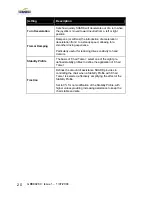
Setting
Description
Lowest Forward
Speed
The maximum speed SHARK will drive with the joystick full
forward, and the speed dial fully counter-clockwise.
Lowest Turn Speed
The maximum speed SHARK will drive with the joystick full
left or right, and the speed dial fully counter-clockwise.
Sleep Timer
Set the amount of time (in minutes) that SHARK will turn
itself off after no user input. Set to 0 to disable this feature.
Wakeup Style
Defines how a user can wake SHARK out of Sleep mode.
Select Button or Jo Button.
Joystick Throw
Defines the amount of joystick movement required for full
speed. Options are Normal (full deflection), Short or Very
Short.
Lock Enable
Turns the Lock feature On or Off. See Section 2.5 – Locking
SHARK.
Field Programmability
Setting this to ‘Limited’ will disable the Hand Held
Programmer.
Active Drive Program
Defines which of the three available Drive Programs is to be
used. If set to DCI Select 1+2, the DCI Swivel function will
change to a Drive Program Swap mode. Activation of the
DCI Swivel function will change the Active Drive Program
from Drive Program 1 to 2.
Summary of Contents for Hydra C650PW
Page 29: ...29 ...
Page 34: ...7 7 Electromagnetic Compatibility EMC 48 7 8 Contact Details 49 ...
Page 36: ...GBK80260 Issue 1 1 07 2004 2 THIS PAGE IS LEFT BLANK INTENTIONALLY ...
Page 48: ...GBK80260 Issue 1 1 07 2004 14 THIS PAGE IS LEFT BLANK INTENTIONALLY ...
Page 64: ...GBK80260 Issue 1 1 07 2004 30 THIS PAGE IS LEFT BLANK INTENTIONALLY ...
Page 66: ...GBK80260 Issue 1 1 07 2004 32 THIS PAGE IS LEFT BLANK INTENTIONALLY ...
Page 71: ...Chapter 7 Appendices 37 Dynamic SHARK Looms For DK REMA DK PMA Power Module ...
Page 84: ...Installation Manual DK PMA SHARK Power Module by GBK80262 Issue 1 June 2004 ...
Page 87: ......
Page 89: ...GBK80262 Issue 1 1 07 2004 2 THIS PAGE IS LEFT BLANK INTENTIONALLY ...
Page 91: ...GBK80262 Issue 1 1 07 2004 4 THIS PAGE IS LEFT BLANK INTENTIONALLY ...
Page 113: ...GBK80262 Issue 1 1 07 2004 26 Dynamic SHARK DK PMA Looms ...
Page 116: ...Chapter 7 Appendices 29 Dynamic SHARK Connector Kits and Adapters ...


