background image

Operation

5 Operation

5.1 Introduction

The operation of the patient lift is an easy and safe procedure.

Before using the lift with a patient, refer to the following
procedures for safety information and instruction:

2.2 Operating Information, page 6

6.4 Lifting and Transferring the Patient, page 31

5.2 Closing/Opening Legs

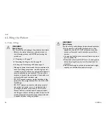
WARNING!
Risk of Injury

The lift could tip and endanger the patient and assistants.

The legs of the lift must be in the maximum open

position for optimum stability and safety. If it is
necessary to close the legs of the lift to maneuver the
lift under a bed, close the legs of the lift only as long as
it takes to position the lift over the patient and lift the
patient off the surface of the bed. When the legs of
the lift are no longer under the bed, return the legs of
the lift to the maximum open position.

The shifter handle must be locked in place for optimum

stability and safety.

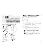
Closing/Opening Manual Legs

The shifter handle is used to open or close the legs of the base for
stability when lifting a patient.

Refer to the safety information in 5.2 Closing/Opening Legs,
page 19 before performing this procedure.

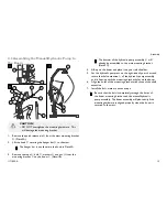
1.

Stand at the rear of the patient lift and grasp the shifter handle
with one hand and place the opposite hand on the steering
handle of the mast for balance.

The shifter handle MUST lock into its mounting slot to lock
the legs in the full closed position.

1171892-A

19

Summary of Contents for I-Lift ILIFTEE

Page 1: ...FTEM ILIFTEE EN Portable Patient Lift User Manual 3 FC L ve personne portatif Manuel d utilisation 55 This manual MUST be given to the user of the product BEFORE using this product read this manual an...

Page 2: ...ation duplication or modification in whole or in part is prohibited without prior written permission from Invacare Trademarks are identified by and All trademarks are owned by or licensed to Invacare...

Page 3: ...4 8 Resetting the Service Light 18 5 Operation 19 5 1 Introduction 19 5 2 Closing Opening Legs 19 Closing Opening Manual Legs 19 Closing Opening Electric Legs 20 5 3 Raising Lowering the Lift 21 Rais...

Page 4: ...Maintaining the Base Adjustment 45 8 14 Replacing Rear Casters 46 8 15 Replacing Front Casters 46 9 Scale 47 9 1 Scale Introduction 47 9 2 Removing the Swivel Bar 47 9 3 Installing the Scale 48 9 4 O...

Page 5: ...tes a potentially hazardous situation which if not avoided could result in death or serious injury CAUTION Caution indicates a potentially hazardous situation which if not avoided may result in proper...

Page 6: ...ting Information This section of the manual contains general safety information about your product For specific safety information refer to the appropriate section of the manual and procedures within...

Page 7: ...lity and obligation of the customer to contact a qualified electrician and have the two prong receptacle replaced with a properly grounded three prong wall receptacle in accordance with the National E...

Page 8: ...in normal household waste They MUST be taken to a proper disposal site Contact your local waste management company for information Please be environmentally responsible and recycle this product throu...

Page 9: ...Safety 2 4 Product Labeling Electric lift shown Locations are the same on the hydraulic manual lift 1171892 A 9...

Page 10: ...ster Size 3 94 in 100 mm Sling Options 3 Styles 3 Styles 1 Style Turning Diameter 57 in 1450 mm 57 6 in 1464 Max Lifting Capacity Weight Capacity 450 lb 205 kg Total Weight 110 lb 49 9 kg 117 5 lb 53...

Page 11: ...ize M L XL M L XL N A N A Width 41 5 45 5 45 5 41 5 45 4 45 5 45 45 Commode Opening N A N A N A 8 8 9 N A 7 Length 54 7 60 5 65 3 54 7 60 5 65 3 55 55 Commode Opening N A N A N A 11 11 13 N A 13 Back...

Page 12: ...2 35 7 41 7 43 2 N A Weight Capacity lbs 450 450 450 450 450 All dimensions are in inches except where noted 3 4 I Lift Scale ILS450 Weight Range Up to 600 lbs 272 7 Kg Resolution 0 2 lbs 1 Kg Displa...

Page 13: ...NOT overtighten the mounting hardware This will damage the mounting bracket 4 2 Assembling the Mast to the Base 1 Lock rear casters A Detail A 2 Remove the shoulder bolt B nut C and washers D from the...

Page 14: ...I Lift 14 1171892 A...

Page 15: ...ll already be assembled to the mast mounting bracket Detail C 4 Lift up on the boom and place it on your left shoulder 5 Let the hydraulic pump rest on the right side of your chest and rotate the shaf...

Page 16: ...tuator rest on your right side of your chest and rotate the shaft extension L of the actuator assembly until it lines up with the mounting holes in the boom assembly 6 Align the holes of the boom asse...

Page 17: ...and secure with hitch pins E 2 Connect the leg actuator cable F to the bottom of the control box G 3 Ensure the actuator plug is fully pushed into the control box 4 Check the service light Refer to 4...

Page 18: ...mbly Reassembly Flashing Reset the service light Refer to 4 8 Resetting the Service Light page 18 The lift requires service Contact your local Invacare dealer for service Not Flashing The lift is read...

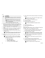
Page 19: ...ft only as long as it takes to position the lift over the patient and lift the patient off the surface of the bed When the legs of the lift are no longer under the bed return the legs of the lift to t...

Page 20: ...the shifter handle away from the patient lift and then to your left until it locks in the notch of the bracket b Opening the Legs B Pull the shifter handle away from the patient lift and then to your...

Page 21: ...efore performing this procedure There are two controls on the pump assembly The control valve The pump handle 1 To raise the lift a Position the control valve in the closed position A towards the pump...

Page 22: ...UP A button to raise the boom and the patient 2 To lower the lift Press the DOWN B button to lower the boom and the patient 5 4 Activating a Mechanical Emergency Release There are two types of mechan...

Page 23: ...es where the primary release is either not functioning or unreachable a secondary emergency release may be used 1 Pull up on the EMERGENCY grip A and push down on the boom B at the same time 5 5 Perfo...

Page 24: ...holes 7 Install the two remaining mounting screws D through the mounting bracket and into the wall Tighten securely 8 Plug the battery charger into the wall electrical outlet ON LED should illuminate...

Page 25: ...the battery 5 Lift the battery up and out away from the battery charger CAUTION Mounting the battery improperly may cause injury or damage Make sure there is an audible click when mounting battery on...

Page 26: ...limitation for the I Lift is 450 lbs 205 kg DO NOT attempt any transfer without approval of the patient s physician nurse or medical assistant Thoroughly read the instructions in this Owner s Manual o...

Page 27: ...mum open position for optimum stability and safety If it is necessary to close the legs of the lift to maneuver the lift under a bed close the legs of the lift only as long as it takes to position the...

Page 28: ...he steering handle to push the patient lift into position 5 Lower the patient lift for easy attachment of the sling 6 Lock the rear casters 7 Proceed to 6 4 Lifting and Transferring the Patient page 3...

Page 29: ...perly attached before the patient is removed from a stationary object bed chair or commode WARNING If the patient is in a wheelchair secure the wheel locks in place to prevent the chair from moving fo...

Page 30: ...t Model Nos R110 R117 Full Body Slings and Model Nos R120 R122 Toileting Slings have four sling straps two per side See Detail A Model Nos R100 R102 Divided Leg Slings have six sling straps three per...

Page 31: ...ving the sling from around the patient Invacare does recommend that the rear casters be left unlocked during lifting procedures to allow the patient lift to stabilize itself when the patient is initia...

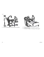
Page 32: ...cedure Bed Transfer page 33 Floor Transfer page 32 Wheelchair Transfer page 34 Commode Transfer Guidelines page 33 9 Raise or lower the lift to position the patient over the stationary surface Be sure...

Page 33: ...o 5 3 Raising Lowering the Lift page 21 4 Both assistants should help guide the patient onto the commode 5 Lower the patient onto the commode leaving the sling attached to the hanger bar hooks Invacar...

Page 34: ...the seat with their back against the back of the chair 3 Begin to lower the patient either by opening the control valve or by pressing the DOWN button 4 With one assistant behind the chair and the oth...

Page 35: ...sters page 46 Noisy or dry sound from pivots Needs lubrication Refer to 8 3 Lubricating the Lift page 39 Oil leaking from hydraulics Hydraulic pump in need of replacement Refer to 8 7 Replacing a Manu...

Page 36: ...to 8 9 Replacing the Electric Actuator page 42 or 8 10 Replacing the Leg Actuator page 43 Contact your Dealer Unusual noise from actuator Actuator is worn or damaged or spindle is bent Refer to 8 7 R...

Page 37: ...aintenance procedures described in this manual to keep your patient lift in continuous service The Invacare Patient Lift is designed to provide a maximum of safe efficient and satisfactory service wit...

Page 38: ...sure proper connection and patient safety q Inspect sling material for wear q Inspect straps for wear THE BOOM q Check all hardware and hanger bar supports q Inspect for bends or deflections q Inspect...

Page 39: ...used until repairs are made 8 5 Cleaning the Sling and Lift The sling should be regularly washed in water temperature not to exceed 180 F 82 C and a biocidal anti biological solution A soft cloth damp...

Page 40: ...the mounting hardware This will damage the mounting bracket 1 Loosen the nut A that secures the ball of the pump B into the mounting socket C 2 Rest the boom D on your shoulder and remove the nut F b...

Page 41: ...to the ILIFTHM models only 1 Turn the control valve A so it will clear the pump handle B when the handle is fully retracted 2 Loosen the set screw C a few turns 3 Remove the control valve lever 4 Hand...

Page 42: ...cket N 3 Remove the electric actuator 4 Reverse STEPS 1 3 for installation CAUTION Risk of Damage Improper assembly may cause injury or damage DO NOT overtighten the mounting hardware This will damage...

Page 43: ...onnel or damage to the patient lift may occur Ensure that there is sufficient room to turn the patient lift on its side and that the floor area is clear of debris a Turn the patient lift on its side b...

Page 44: ...y cause injury to the patient or assistants After the first year of use the hooks of the hanger bar and mounting brackets of the boom should be inspected every six months to determine the extent of we...

Page 45: ...kage rods 1 Close the legs all the way Refer to Closing Opening Manual Legs page 19 or Closing Opening Electric Legs page 20 2 Check the squareness of the legs B when in the closed position 3 Place a...

Page 46: ...the rear caster bracket bearing and new rear caster and tighten securely with the locknut 8 15 Replacing Front Casters 1 Place the lift on its side 2 Remove the bolt A bearing C and locknut B that sec...

Page 47: ...rnings Cautions or Instructions contact a healthcare professional dealer or technical personnel before attempting to install this equipment otherwise injury or damage may occur Patient and sling MUST...

Page 48: ...oad cell assembly A of the scale into the boom mounting bracket B 3 Secure the scale to the boom mounting bracket with the clevis pin C two spacers D and the clip E 4 Secure the hanger bar F to the sc...

Page 49: ...will reset the weight shown in the display window to zero UNITS lb or kg Upper Right Corner of the Display Window The function of this key is to change the unit of measurement from pounds lb to kilogr...

Page 50: ...on will then be turned off and the word LOCK will disappear from the display The scale is now active and continually updating the weight display 4 Place the patient in the sling 5 Attach the sling to...

Page 51: ...cement When battery replacement is needed lo bat will appear on the display Perform the following 1 Slide the battery door A open in the direction of the arrow B 2 Remove existing battery 3 Install th...

Page 52: ...d press the ZERO key b FOR CAL2 OPTION support 200 pounds of calibrated weight from the scale and press the ZERO key 8 The display window will show a dashed line scrolling across and then the word DON...

Page 53: ...ays of return authorization date Do not return products to our factory without our prior consent C O D shipments will be refused please prepay shipping charges LIMITATIONS AND EXCLUSIONS THE FOREGOING...

Page 54: ...tand q q Are there too many warnings cautions q q Are there warnings cautions that you feel do not apply to this product q q Explain ____________________________________________________________ ______...

Page 55: ...e de l embrayeur 71 4 7 V rification du t moin de service 72 4 8 R initialisation du t moin de service 72 5 Fonctionnement 74 5 1 Introduction 74 5 2 Fermeture et ouverture des pattes 74 Ouverture et...

Page 56: ...l actionneur de pattes 100 8 11 V rification et serrage de l axe de pivot du m t 101 8 12 Remplacement du support pivotant 101 8 13 Entretien et alignement de la base 102 8 14 Remplacement des roulet...

Page 57: ...tuation dangereuse qui si elle n est pas vit e pourrait causer de graves blessures voire la mort ATTENTION Mise en garde indique l imminence d une situation dangereuse qui si elle n est pas vit e pour...

Page 58: ...ent con us et fabriqu s pour tre utilis s avec les accessoires Invacare Les accessoires con us par d autres fabricants n ont pas t mis l essai par Invacare et leur utilisation avec les produits Invaca...

Page 59: ...vement et ex cuter toute cette proc dure plusieurs fois sous supervision avec un individu en bonne sant jouant le r le du patient Les toiles et accessoires du l ve personne de Invacare sont con us sp...

Page 60: ...de la position du cintre et du patient Des blessures peuvent se produire lectricit et mise la terre AVERTISSEMENT INSTRUCTIONS DE MISE LA TERRE NE PAS couper et NE PAS enlever sous aucune consid rati...

Page 61: ...pas compl tement dans la prise Si la fiche ne s ins re toujours pas communiquer avec un lectricien qualifi et faire installer une prise murale ad quate NE PAS modifier la fiche d aucune mani re Mise...

Page 62: ...faut tre PRUDENT lorsqu on utilise de l quipement de communication portatif proximit de tels appareils Si les perturbations radio lectriques provoquent une instabilit APPUYER IMM DIATEMENT sur la pos...

Page 63: ...S curit 2 4 tiquetage du produit Illustration du l ve personne lectrique Les emplacements sont identiques sur les l ve personne hydraulique et manuel 1171892 A 63...

Page 64: ...mension des roulettes 10 cm 3 94 po Options de la toile 3 styles 3 styles 1 style Diam tre de virage 1 450 m 57 po 1 464 m 57 6 po Capacit de soul vement max capacit pond rale 205 kg 450 lb Poids tota...

Page 65: ...e p rin ale S O S O S O 20 3 cm 8 po 20 3 cm 8 po 22 9 cm 9 po S O 17 8 cm 7 po Longueur 138 9 cm 54 7 po 153 7 cm 60 5 po 165 9 cm 65 3 po 138 9 cm 54 7 po 153 7 cm 60 5 po 165 9 cm 65 3 po 139 7 cm...

Page 66: ...7 cm 35 7 po 105 9 cm 41 7 po 109 7 cm 43 2 po S O Capacit pond rale 205 kg 450 lb 205 kg 450 lb 205 kg 450 lb 205 kg 450 lb 205 kg 450 lb Toutes les dimensions sont indiqu es en centim tres et en pou...

Page 67: ...uritaire NE PAS serrer excessivement la quincaillerie de montage Un serrement excessif endommagera le support de fixation 4 2 Installation du m t sur la base 1 Verrouiller les roulettes arri re A D ta...

Page 68: ...I Lift 68 1171892 A...

Page 69: ...mpe hydraulique K est d j assembl e au support de fixation du m t D tail C 4 Relever vers le bras et d poser sur l paule gauche 5 Laisser reposer la pompe hydraulique sur le c t droit du torse et tour...

Page 70: ...c t droit du torse et tourner l arbre rallonge L de l assemblage de l actionneur jusqu ce qu il s aligne avec les trous de montage situ s sur l assemblage du bras 6 Aligner les trous du support de fi...

Page 71: ...t c Ins rer la clavette D dans les trous le l actionneur de pattes et du support de fixation du m t et s curiser avec les pingles de blocage E 2 Brancher le c ble de l actionneur de pattes F au bas de...

Page 72: ...mbler le l ve personne 2 Examiner la boite de commande A et s assurer que le t moin de service B clignote 3 Consulter le tableau T moin de service Premier assemblage R assemblage Clignotement R initia...

Page 73: ...uelle A 2 Appuyer et maintenir simultan ment le bouton UP vers le haut enfonc B et le bouton DOWN vers le bas C pendant cinq secondes Un signal sonore se fera entendre lorsque le t moin de service apr...

Page 74: ...attes du l ve personne doivent tre referm es afin de pouvoir manoeuvrer le l ve personne sous un lit et les tenir ferm es aussi longtemps qu il faut pour positionner le l ve personne au dessus du pati...

Page 75: ...ttes du l ve personne soient correctement verrouill es 2 Ex cuter l une des proc dures suivantes a Fermeture des pattes A Tirer et loigner la poign e de l embrayeur du l ve personne vers la gauche jus...

Page 76: ...ient d verrouill es lors du soul vement du patient pour permettre la stabilisation du l ve personne lorsque le patient est soulev d une chaise d un lit ou d un objet fixe l vation et descente du l ve...

Page 77: ...sur le bras pour descendre le l ve personne La vitesse de descente du bras est contr l e par la distance d ouverture de la soupape de commande Une marge de s curit du syst me hydraulique contr le la v...

Page 78: ...ncy Down descente d urgence B sur la boite de commande C D verrouillage d urgence secondaire Il est recommand d utiliser le d verrouillage d urgence principal Le d verrouillage d urgence secondaire n...

Page 79: ...on d sir e 2 l aide d un crayon faire une marque au centre du trou B 3 Mesurer 16 5 cm 6 po au bas du trait de crayon et percer un trou de montage 4 Installer la vis de montage inf rieure Cjusqu ce qu...

Page 80: ...la pile sur le chargeur D comme illustr S assurer que l enclenchement clic se produit La DEL de charge s allumera La DEL s teint d s que la charge est termin e Une charge compl te de la pile dure env...

Page 81: ...tenter le transfert d un patient sans l accord de son m decin de l infirmier ou du pr pos Lire attentivement les instructions contenues dans le manuel de l utilisateur observer une quipe d experts lo...

Page 82: ...rit optimales Les pattes du l ve personne doivent tre referm es afin de pouvoir manoeuvrer le l ve personne sous un lit et les tenir ferm es aussi longtemps qu il faut pour positionner le l ve personn...

Page 83: ...direction pour pousser le l ve personne sa position 5 Descendre le l ve personne pour faciliter l accrochage de la toile 6 Verrouiller les roulettes arri re 7 Proc der selon l article 6 4 Soul vement...

Page 84: ...de d placer le patient partir d un objet fixe lit chaise chaise d aisance Si le patient est en fauteuil roulant enclencher le verrou des roues afin de pr venir le d placement du fauteuil AVERTISSEMEN...

Page 85: ...R120 R122 Toiles hygi niques avec quatre sangles deux de chaque c t Voir D tail A Nos de mod les R100 R102 Toiles double cuissarde avec six sangles trois de chaque c t Voir D tail B Le l ve personne s...

Page 86: ...lettes pivotantes arri re uniquement au moment d installer le patient dans la toile et de l en sortir Invacare RECOMMANDE que les roulettes arri re soient d verrouill es lors du soul vement du patient...

Page 87: ...ilit pour que le patient se sente plus en s curit et facilite le d placement du l ve personne 8 D placer le l ve personne en tenant fermement la manette de direction avec les deux mains Lire et compre...

Page 88: ...e transport de longue distance Si la salle de bains est loin du lit ou si le l ve personne ne peut tre facilement manoeuvr pr s de la chaise d aisance le patient DOIT tre transf r vers un fauteuil rou...

Page 89: ...ient d une surface inf rieure celle du lit appuyer sur le bouton fl che vers le haut pour soulever le patient au dessus de la surface du lit Le patient devrait tre soulev suffisamment du lit pour le s...

Page 90: ...t au dessus du si ge et son dos contre le dossier de la chaise 3 Commencer abaisser le patient en utilisant la soupape de commande ou en appuyant sur le bouton DOWN descente 4 Un pr pos se place derri...

Page 91: ...rin ants Une lubrification est requise Consulter l article 8 3 Lubrification du l ve personne page 96 Fuite d huile des parties hydrauliques La pompe hydraulique doit tre remplac e Consulter l article...

Page 92: ...icle 5 7 Charge de la pile page 80 L actionneur lectrique refuse le hisser ou les pattes ne s ouvrent pas lorsque l on appuie sur le bouton Le bras ou l actionneur de pattes requiert une r paration ou...

Page 93: ...Consulter l article 8 11 V rification et serrage de l axe de pivot du m t page101 La pompe hydraulique se d phase lors d une charge partielle La soupape de commande est peut tre d r gl e Consulter l a...

Page 94: ...rsonne Respecter les proc dures d entretien d crites dans ce manuel afin d assurer le fonctionnement continu du l ve personne Le l ve personne de Invacare est con u pour offrir un service s curitaire...

Page 95: ...assurer qu elles sont fonctionnelles et s curitaires pour le patient q Inspecter l usure du mat riau de la toile q Inspecter l usure des sangles BRAS q V rifier toute la quincaillerie et les supports...

Page 96: ...personne n est pas utilis jusqu ce qu il soit r par 8 5 Nettoyage de la toile et du l ve personne Le l ve personne doit tre lav p riodiquement l eau dont la temp rature ne d passe pas 82 C 180 F avec...

Page 97: ...nt la quincaillerie de montage Un serrement excessif endommagera le support de fixation 1 D visser l crou A s curisant la sph re de la pompe B la douille de montage C 2 Faire reposer le bras D sur l p...

Page 98: ...pape de commande A afin de d gager la poign e de pompe B lorsque cette derni re est compl tement escamot e 2 D visser la vis de r glage C sur quelques tours 3 Retirer le levier de la soupape de comman...

Page 99: ...tirer l actionneur lectrique 4 Inverser les TAPES 1 3 pour l installation ATTENTION Risque de dommages Un assemblage incorrect peut causer des blessures ou des dommages NE PAS serrer excessivement la...

Page 100: ...euvent survenir pour les pr pos s et des dommages au l ve personne peuvent survenir S assurer d un espace suffisant pour coucher le l ve personne sur le c t et que le sol est libre de d bris a Coucher...

Page 101: ...nne peuvent causer des blessures au patient et aux pr pos s Apr s la premi re ann e d utilisation les crochets du cintre et les supports de fixation du bras doivent tre inspect s tous les six mois afi...

Page 102: ...chapitre Ouverture et fermeture manuelle des pattes page 74 ou Ouverture et fermeture lectrique des pattes page 75 2 V rifier la perpendicularit des pattes B lorsque ces derni res sont en position fe...

Page 103: ...ort de roulette arri re le palier et la roulette arri re neuve et serrer fermement avec l crou frein 8 15 Remplacement des roulettes avant 1 Coucher le l ve personne sur le c t 2 Retirer le boulon A l...

Page 104: ...ez pas les avertissements mises en garde et instructions avant toute tentative d installation de cet quipement pour viter tout risque de blessures ou de dommages Le patient ne doit pas tre install dan...

Page 105: ...ule de charge A du p se personne sur le support de fixation du bras B 3 S curiser le p se personne au support de fixation du bras avec l axe d articulation C les deux entretoisesD et la pince E 4 S cu...

Page 106: ...onne sous tension Quand le p se personne d j sous tension il suffit d appuyer sur cette touche pour l teindre ZERO ZERO Coin inf rieur gauche de l afficheur Appuyer sur cette touche lorsque le p se pe...

Page 107: ...ochets du mod le I Lift des deux c t s du cintre permet une plus grande pr cision Toutefois il se peut que le confort du patient exige une configuration de sangles de la toile diff rente 2 Appuyer sur...

Page 108: ...b le p se personne varie de 99 8 100 2 45 2 45 4 g jusqu ce qu on appuie sur le bouton LOCK verrouiller Une telle fluctuation est normale Appuyer sur la touche LOCK pour verrouiller le poids 9 Le l ve...

Page 109: ...de circuits imprim s Apr s avoir appuy sur le bouton CAL CAL1 s affichera l cran CAL1 s lectionne le mode d talonnage avec un talon de 22 65 kg 50 lb CAL2 s lectionne le mode d talonnage avec un talo...

Page 110: ...p se personne est maintenant en mode de fonctionnement normal 9 8 D pannage SYMPT ME CAUSE PROBABLE SOLUTIONS L appareil NE fonctionne PAS correctement Pile d fectueuse V rifier la pile Remplacer au...

Page 111: ...e le cas ch ant aux fins d identification dans les trente jours suivants la date d autorisation du retour NE PAS retourner de produit notre usine sans autorisation pr alable Les livraisons contre remb...

Page 112: ...I Lift MENTIONN ES CI DESSUS PEUVENT NE PAS S APPLIQUER DANS VOTRE CAS CETTE GARANTIE SERA ADAPT E AFIN DE R PONDRE AUX LOIS ET R GLEMENTS PROVINCIAUX ET NATIONAUX 112 1171892 A...

Page 113: ...Notes...

Page 114: ...Notes...

Page 115: ......

Page 116: ...ustrial Park Suzhou Jiangsu PRC 215021 Tel 86 512 62586192 Fax 86 512 62586072 Invacare Corporation USA One Invacare Way Elyria Ohio USA 44036 2125 800 333 6900 Canada 570 Matheson Blvd E Unit 8 Missi...

Reviews: