background image

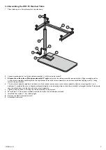
4.2 Assembling the IH5135 Overbed Table

1.

Place table top on a flat stable surface top side down.

G

D

I

F

A

B

C

H

E

2.

Loosen mounting bolts

A

until the column assembly

B

will fit into top bracket

C

.

3.

Elevate the release lever

D

D

D

to approximately 45° angle

and insert the column assembly into top bracket. Align rectangle notches

on the column assembly with dimples on the top bracket. Ensure the column assembly is set in place with black shipping screw

E

facing

toward the top bracket.

4.

Tilt the column assembly slightly in the direction of the release lever and secure the column assembly with the mounting plate

F

and

hardware

A

provided. Be sure to align the embossed dimples in the mounting plate to the column assembly rectangular notches. Also ensure

that the release lever is in the channel in the column assembly.

5.

Tighten mounting bolts

A

securing the column assembly to top bracket.

6.

Secure base

G

to the column assembly with the bolt plate

H

and hardware provided.

7.

Install the four casters

I

. Set table upright.

8.

Remove the black screw and discard.

9.

Assembly is complete.

1192682-A~01

5

Summary of Contents for IH1010

Page 1: ...ch could result in personal injury or property damage DANGER Danger indicates an imminently hazardous situation which if not avoided will result in death or serious injury WARNING Warning indicates a...

Page 2: ...ts repair or service and before use DO NOT use product if parts are damaged or defective WARNING Risk Of Injury or Damage The column assembly is spring loaded and will extend suddenly when the shippin...

Page 3: ...gh Pressure Laminate Height Range 28 45 inches 30 45 inches 15 one inch increments Weight Capacity 50 pounds 100 pounds Caster Size 1 5 inches 2 inches Base Clearance 24 inches 28 inches Frame Materia...

Page 4: ...embly B and insert into table top bracket C 4 Align holes on the column assembly including release lever with those of table top bracket and secure the column assembly with hardware D provided 5 Secur...

Page 5: ...screw E facing toward the top bracket 4 Tilt the column assembly slightly in the direction of the release lever and secure the column assembly with the mounting plate F and hardware A provided Be sure...

Page 6: ...n the overbed table 6 2 Maintenance The product is maintenance free provided the cleaning and safety instructions are followed at least every six 6 months Check product regularly for damage and to ens...

Page 7: ...Notes...

Page 8: ...ges LIMITATIONS AND EXCLUSIONS THE WARRANTY SHALL NOT APPLY TO PROBLEMS ARISING FROM NORMAL WEAR OR FAILURE TO ADHERE TO THE ENCLOSED INSTRUCTIONS IN ADDITION THE FOREGOING WARRANTY SHALL NOT APPLY TO...

Reviews: